18
Bentone B55/B65
General
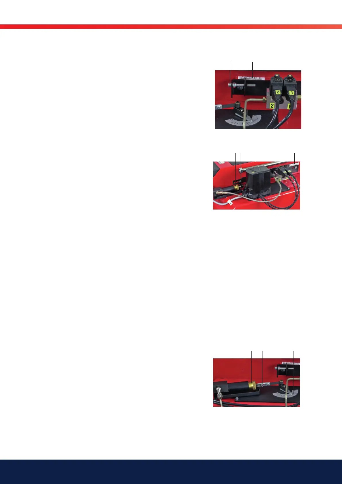
4.6 Nozzle assembly regulation –
fixed brake plate
Nozzle assembly regulation is used to achieve the most favourable
pressure drop possible across the brake plate.
Nozzle assembly regulation should be adjusted for Stage 2 output
Adjustment
Adjust to the desired position on the scale (A) using the set screw (B)
(turning anti-clockwise reduces the pressure drop and moves the brake
plate outwards).
If pulsation occurs, the pressure drop across the brake plate can be alte-
red until pulsation stops.
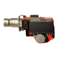
4.7 Nozzle assembly regulation –
adjustable brake plate
Nozzle assembly regulation is used to achieve the most favourable
pressure drop possible across the brake plate for each output stage.
Two nozzles
Nozzle assembly regulation adjusts the position of the brake plate between
Stage 1 and Stage 2 by means of a hydraulic piston.
Three nozzles
Nozzle assembly regulation adjusts the position of the brake plate between
Stage 2 and Stage 3 by means of a hydraulic piston.
Low load
Undo the locking nut.
Adjust to the desired position on the scale (A) by sliding the plate to the
desired position. Tighten the locking nut (C).
High load
Adjust to the desired position on the scale (A) using the set screw (D)
(turning anti-clockwise reduces the pressure drop and moves the brake
plate outwards). If pulsation occurs, the pressure drop across the brake
plate can be alte-red until pulsation stops.
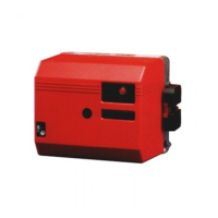
4.8 Hydraulic air adjustment
Stage 1
Set the control switch (S2) to low load (I). Undo the screw (E), turn the
damper to the desired position and retighten the screw (E).
Stage 2
Set the control switch (S2) to high load (I). Use the adjuster pin to screw
the sleeve (F) in (to reduce) or out (to increase). The position of the dam-
per can be read from the damper scale (G). Carry out flue gas analysis to
check the air settings
C AD
EF G
AB