25
Bentone B55/B65
General
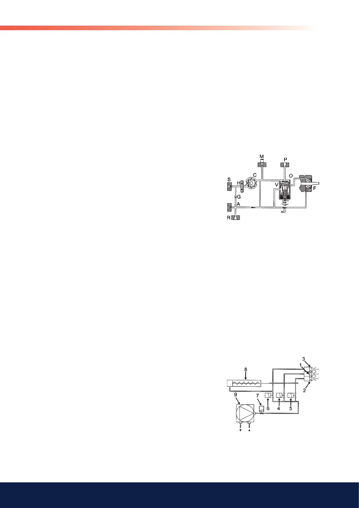
6.6 Function Danfoss RSA 95 - 125
When the pump is started oil is drawn through the suction port ”S” via filter
”H” to the suction side of the gearwheel set ”C”. From here the gearwheel
set pumps the oil to the pressure side and at the same time the oil becomes
pressurized. The oil is led to cut-off and regulating valve ”V” which opens
when the set pressure is reached.
The pressure is controlled and kept constant by regulating valve ”V”. At the
same time the gearwheel set ”C” distributes the oil through nozzle port ”P”
and pump return side ”R” via the shaft seal ”F”.
The quantity of oil supplied to nozzle port ”P” is determined by the pressure
set on regulating valve ”V” and the nozzle/resistance in the nozzle line.
In 2-pipe-systems excess oil is led back to the oil tank. In 1-pipe-systems
the by-pass plug ”A” must be removed to give free flow back to the suction
side via return line ”G” with return port ”R” closed.
When the pump is stopped, the pump output drops and produces a drop
in the oil pressure. The spring in the regulating valve presses the regulating
piston forward until it seals in port ”P”. This cuts off the oil flow to the nozzle
and ensures that the nozzle line is effectively shut off.
If the pump is overloaded, i.e. more oil is demanded than the gearwheel is
able to pump under the given conditions, the oil pressure falls below the set
value because the piston of the regulating valve moves towards its closed
position and partially or wholly cuts off the return oil via port ”O”.
This can be remedied by
• reducing the pump pressure
• reducing the capacity, i.e. smaller nozzle or greater resistance
• changing to a pump with higher capacity
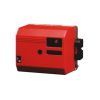
Schematic diagram
1. Nozzle Stage 1
2. Nozzle Stage 2
3. Nozzle Stage 3
4. Solenoid valve Stage 1 (Y1)
5. Solenoid valve Stage 2 (Y2)
6. Solenoid valve Stage 3 (Y3)
7. Safety valve for nozzle (Y1S)
Only for capacities over 100 kg/h or on special request by customer
8. Hydraulic control device
Only on burners with hydraulic air control or nozzle assembly
optimisation.
9. Oil pump
Items 3 and 6 are not fitted to two-stage burners. Item 8 is connected after
solenoid valve nozzle 2 (Y2).