Home
Bentone
Burner
B55
Page 17 (Set Values for Nozzle Assembly B55)
Bentone B55 - Set Values for Nozzle Assembly B55; Set Values for Nozzle Assembly B65; Set Values for Air Damper B55; Set Values for Air Damper B65
44 pages
Manual
Save Page as PDF
To Next Page
To Next Page
To Previous Page
To Previous Page
Loading...
17
Bentone B55/B65
General
4.2
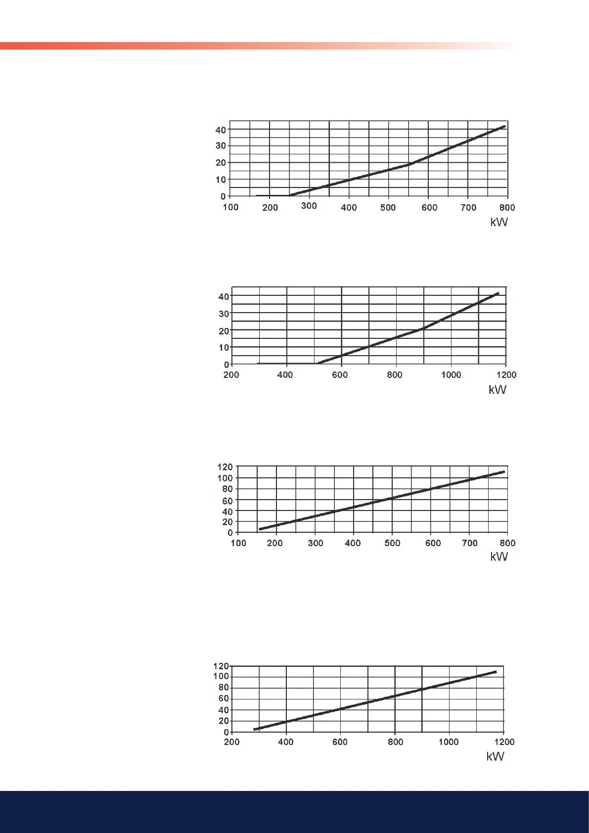
Set values for nozzle assembly B55
4.3
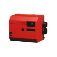
Set values for nozzle assembly B65
4.4
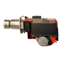
Set values for air damper B55
4.5
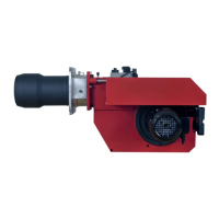
Set values for air damper B65
Air
, <°
Air
, <°
Scale, nozzle assembly
Scale, nozzle assembly
16
18
Table of Contents
Main Page
Default Chapter
3
Table of Contents
3
Description
8
2 Technical Data
10
Type Designation B55-2H/B55-2/B55-2R/B55-3R/ B65-2H/B65-2/B65-2R/B65-3R
10
Dimensions
10
Recommended Nozzle and Pressure
10
Output Range and Nozzles Recommended
10
Working Ield
11
Nozzle Table
12
Nozzle Table
13
3 Installation
14
Acceptance Inspection
14
Preparations for Installation
14
Distribution of Oil
14
Electrical Connections
14
Choice of Nozzle
14
Setting of the Brake Plate and Air Low
14
Burner Installation
15
Hole Pattern
15
Installing the Burner
15
Oil Lines
15
Electrical Connections
15
4 Basic Settings
16
Typical Basic Settings for B65-2H/B65-2
16
B65-2R/B65-3R
16
Set Values for Nozzle Assembly B55
17
Set Values for Nozzle Assembly B65
17
Set Values for Air Damper B55
17
Set Values for Air Damper B65
17
Nozzle Assembly Regulation - Ixed Brake Plate
18
Nozzle Assembly Regulation - Adjustable Brake Plate
18
Hydraulic Air Adjustment
18
Damper Motor 2-Stage
19
Damper Motor 3-Stage
20
5 Maintenance
21
Servicing the Burner Device
21
Adjusting the Ignition Electrodes and Brake Plate
21
Servicing the Air Damper
22
Replacing the Damper Motor
22
Replacing the Oil Pump
23
6 Instructions Pump
24
Type 95 & 125
24
Components
24
Mounting/Dismounting By-Pass Plug
24
Purging
24
Replacing the Ilter
24
Function Danfoss RSA 95 - 125
25
Suction Line Tables
26
7 Electric Equipment
27
Wiring Diagram LMO24.255
27
Wiring Diagram LAL 1
32
List of Components LAL 1
33
Function LAL 1
34
Wiring Diagram LAL 1
35
Wiring Diagram LAL 1
36
List of Components LAL 1
37
Function LAL 1
38
Control Programme under Fault Conditions and Lock-Out Indication LAL
39
Technical Data LAL 1
39
8 Fault Location
40
Burner will Not Start
40
Burner will Not Start after Normal Use
40
Delayed Ignition, Burner Starts; Pulsation
40
9 Declaration of Conformity
41
Other manuals for Bentone B55
Installation And Maintenance Instructions
32 pages
Related product manuals
Bentone B30
48 pages
Bentone B10E
14 pages
Bentone BG100
58 pages
Bentone BG650
58 pages
Bentone B 30A
40 pages
Bentone BG600
58 pages
Bentone B 70-3
56 pages
Bentone BG 400
48 pages
Bentone BG 700
25 pages
Bentone BG 500
25 pages
Bentone B 30 2A
44 pages
Bentone B 80-3R
56 pages