33 Bentone BF1
General
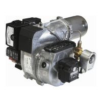
Two pipe lift system
Zweistranginstallation - Tank tiefer als Pumpe
Installation bitube en aspiration
Impianti bitubo in aspirazione
H
H max. = 4,5 m
d
6.1.1.2 Underlying tank
1-pipe system
With an underlying tank a 1-pipe-system is not recommended
Two-pipe system
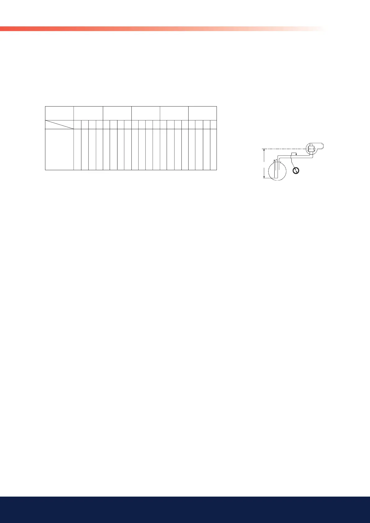
0 15 50 124 150
0,5 13 44 109 150
1 11 38 95 150
2 7 26 66 138
3 3 14 37 79
84 19
11 38 96 150 7 27 71 150 20 54 116 150 16 46 100 150
9 33 84 150 6 24 62 132 17 48 103 150 14 40 88 150
8 29 73 150 4 20 54 115 15 41 89 150 12 34 76 144
5 19 51 107 2 13 37 80 9 28 61 116 7 23 52 100
10 28 60 6 20 44 4 14 33 65 11 28 55
5 14 9 6 14 4 11
d (mm)
35/45 55 65 75 95
60 77 102 130 150
Pump/Pumpe
Pompe/Pompa
Q** (l/h)
6 8 10 12 6 8 10 12 6 8 10 12 8 10 12 14 8 10 12 14
H (m)
The suction line tables consist of theoretically calculated values where the
pipe dimensions and oil velocity have been matched so that tur-bulences will
not occur. Such tur-bulences will result in increased pressure losses and in
acoustic noise in the pipe system. In addition to drawn copper piping a pipe
system usually comprises 4 elbows, a non-return valve, a cut-off valve and
an external oil filter.
The sum of these individual resi-stances is so insignificant that they can be
disregarded. The tables do not include any lengths exceeding 100 m as
experience shows that longer lengths are not needed.
The tables apply to a standard fuel oil of normal commercial quality accor-
ding to current standards. On commis- sioning with an empty tube system
the oil pump should not be run without oil for more than 5 min. (a condition is
that the pump is being lubricated during operation).
The tables state the total suction line length in metres at a nozzle capacity of
9,5 Gph. Max. permissible pressure at the suction and pressure side is 2,0
bar.