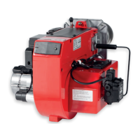
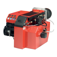
43 Bentone BF1
General
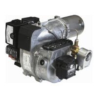
9.1.1 Component list
A1 Oil burner control S3 Operations thermostat
E1 Preheater S4 Temperature limiter
F1 Fuse, max 10 A S7 Main switch
H1 Alarm lamp T1 Ignition transformer
M1 Burner motor Y1 Solenoid valve
P1 Timer (Accessory) X3 Plug-in contact, burner
R1 Flame detector QRB X4 Plug-in contact, boiler
U2 UV-cell QRC
Preheater wiring colours: A Blue B Brown C Black
The installation must be connected to the mains and fused according to local
regulations.
9.1.2 Function LMO1..2..4..
1a. Operations switch ON, thermostat ON
The burner motor starts, ignition sparks initiated and pre-ventilation
continues until the set pre-ventilation period is over and the
solenoid valve (2) opens..
1b. Operations switch ON, thermostat ON
The preheater is energized and the pre-heating period begins.
This continues until the operating temperature is reached and the
preheater thermostat closes. The burner motor starts, ignition
sparks initiated and pre-ventilation continues until the set pre-
ventilation period is over and the solenoid valve (2) opens.
2. Solenoid valve opens
The oil mist is formed and ignited. The photocell indicates flame.
The ignition spark ceases 15 sec. after flame indication.
3.
a
b
Safety period runs out
If the flame is not present before the end of this period, the oil burner
control blocks further operation.
If the flame for any reason disappears after this time period, the
burner will make a new start attempt.
4-5 During operation
If burner operations are interrupted via the main switch or
thermostat, a new start will be initiated when conditions according
to point 1 are fulfilled.
Oil burner control blocks
Red light on the oil burner control illuminates. The burner is re-
started by pressing the reset button.