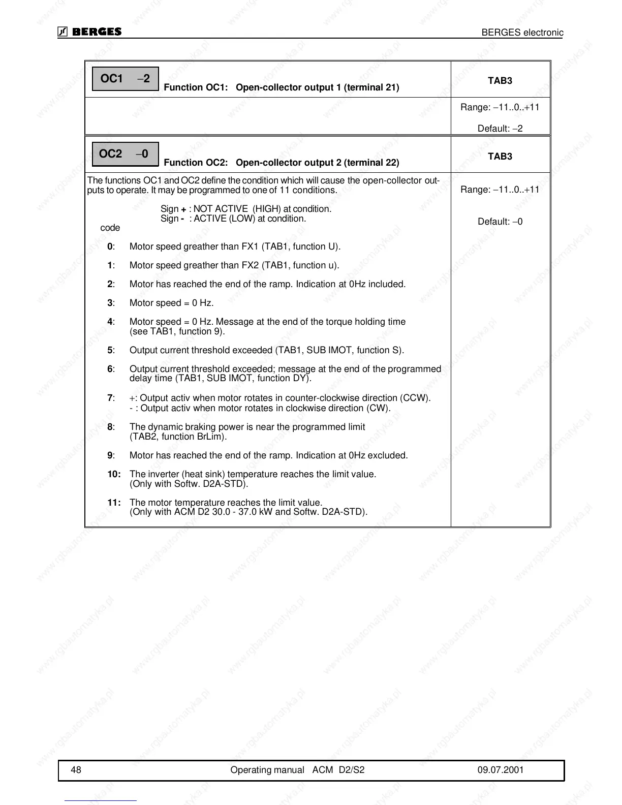
Function OC1: Open-collector output 1 (terminal 21)
TAB3
Range: −11..0..+11
Default: −2
Function OC2: Open-collector output 2 (terminal 22)
TAB3
The functions OC1 and OC2 define the condition which will cause the open-collector out-
puts to operate. It may be programmed to one of 11 conditions.
Sign + : NOT ACTIVE (HIGH) at condition.
Sign - : ACTIVE (LOW) at condition.
code
0: Motor speed greather than FX1 (TAB1, function U).
1: Motor speed greather than FX2 (TAB1, function u).
2: Motor has reached the end of the ramp. Indication at 0Hz included.
3: Motor speed = 0 Hz.
4: Motor speed = 0 Hz. Message at the end of the torque holding time
(see TAB1, function 9).
5: Output current threshold exceeded (TAB1, SUB IMOT, function S).
6: Output current threshold exceeded; message at the end of the programmed
delay time (TAB1, SUB IMOT, function DY).
7: +: Output activ when motor rotates in counter-clockwise direction (CCW).
- : Output activ when motor rotates in clockwise direction (CW).
8: The dynamic braking power is near the programmed limit
(TAB2, function BrLim).
9: Motor has reached the end of the ramp. Indication at 0Hz excluded.
10:The inverter (heat sink) temperature reaches the limit value.
(Only with Softw. D2A-STD).
11:The motor temperature reaches the limit value.
(Only with ACM D2 30.0 - 37.0 kW and Softw. D2A-STD).
Range: −11..0..+11
Default: −0
OC1
−
2
OC2
−
0
BERGES electronic
48 Operating manual ACM D2/S2 09.07.2001