Option REL
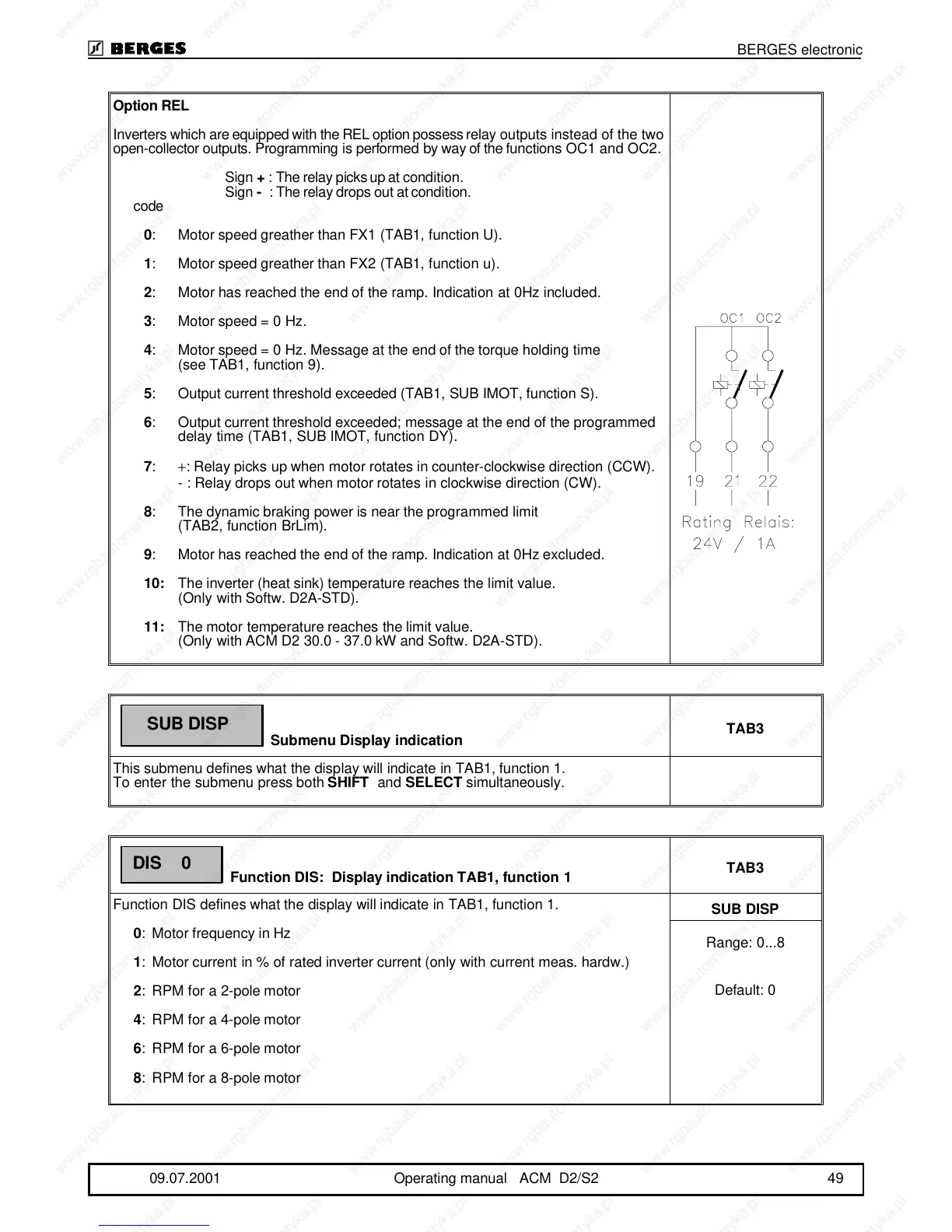
Inverters which are equipped with the REL option possess relay outputs instead of the two
open-collector outputs. Programming is performed by way of the functions OC1 and OC2.
Sign + : The relay picks up at condition.
Sign - : The relay drops out at condition.
code
0: Motor speed greather than FX1 (TAB1, function U).
1: Motor speed greather than FX2 (TAB1, function u).
2: Motor has reached the end of the ramp. Indication at 0Hz included.
3: Motor speed = 0 Hz.
4: Motor speed = 0 Hz. Message at the end of the torque holding time
(see TAB1, function 9).
5: Output current threshold exceeded (TAB1, SUB IMOT, function S).
6: Output current threshold exceeded; message at the end of the programmed
delay time (TAB1, SUB IMOT, function DY).
7: +: Relay picks up when motor rotates in counter-clockwise direction (CCW).
- : Relay drops out when motor rotates in clockwise direction (CW).
8: The dynamic braking power is near the programmed limit
(TAB2, function BrLim).
9: Motor has reached the end of the ramp. Indication at 0Hz excluded.
10:The inverter (heat sink) temperature reaches the limit value.
(Only with Softw. D2A-STD).
11:The motor temperature reaches the limit value.
(Only with ACM D2 30.0 - 37.0 kW and Softw. D2A-STD).
Submenu Display indication
TAB3
This submenu defines what the display will indicate in TAB1, function 1.
To enter the submenu press both SHIFT and SELECT simultaneously.
Function DIS: Display indication TAB1, function 1
TAB3
Function DIS defines what the display will indicate in TAB1, function 1.
0: Motor frequency in Hz
1: Motor current in % of rated inverter current (only with current meas. hardw.)
2: RPM for a 2-pole motor
4: RPM for a 4-pole motor
6: RPM for a 6-pole motor
8: RPM for a 8-pole motor
SUB DISP
Range: 0...8
Default: 0
SUB DISP
DIS 0
BERGES electronic
09.07.2001 Operating manual ACM D2/S2 49