Berges electronic • D–51709 Marienheide-Rodt • Tel. 02264/17-0 • Fax 02264/17126
Operating manual 21.12.98
ACP 3000 — 0.37–15.0 04_GB
12
E. Do not install the inverter in a place subjected to high temperature, high humidity, or ex-
cessive vibration (see Table 2.3, “Ambient Conditions”)
F. The units should never be installed in the proximity of corrosive or flammable gases,
conductive dust or large magnetic and electric fields.
G. Pay close attention during installation to ensuring that no objects (such as drilling swarf,
wire or anything else) fall into the unit. Otherwise, a device fault cannot be excluded,
even after longer periods of operation.
H. Do not use wire end ferrules for the control terminals. The terminals are designed
so that the wires can be inserted in the terminals after twisting the individual
wires.
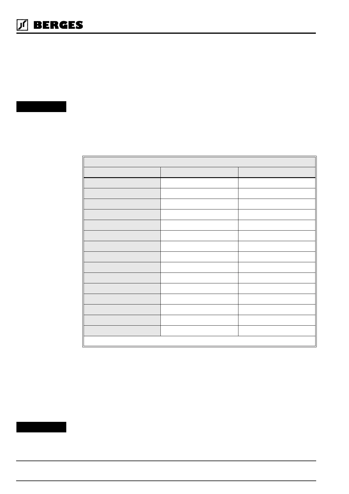
I. Table 3.1 shows the watts generated by the inverter when at full current. The heat gen-
erated is dependent on the carrier frequency used. For carrier frequencies other than
those shown in Table 3.1, consult BERGES or use the worst-case scenario (16 kHz car-
rier).
3.3 EMC (Electromagnetic Compatibility)
3.3.1 Suggestion on how to solve the Problem of Radio Frequency Interference
Suppression of Frequency Converters to VDE 0875/EN 55011
It is necessary to connect a mains filter type “BE/(xxx) xxxx” before every frequency con-
verter. The size (xxx) depends on the rated current of the unit. A motor choke can be dis-
pensed with.
The motor choke type BV... may be necessary as from a cable length in excess of 20 m and
when operating several motors in parallel on one frequency converter output. This choke
attenuates the capacitive earth leakage currents and considerably reduces wire-borne in-
terference voltages.
HEAT GENERATED BY INVERTER (IN WATTS)
Inverter Model Number @ 4 kHz Carrier @ 16 kHz Carrier
3300-3 19 27
3300-5 37 42
3300-7 66 75
3301-1 66 75
3301-5 70 79
3302-2 129 154
3600-7 40 62
3601-5 67 99
3602-2 118 186
3603-0 184 281
3604-0 184 281
3605-5 280 640
3607-5 360 790
3611-0 470 1120
3615-0 610 1400
Table 3.1
ATTENTION!
HINT!