Berges electronic • D–51709 Marienheide-Rodt • Tel. 02264/17-0 • Fax 02264/17126
Operating manual 21.12.98
ACP 3000 — 0.37–15.0 04_GB
34
Help
• For Application Assistance, call BERGES electronic at 02264/17-160, 02264/17-102
and 02264/17-109.
4.9 Quick Start
This section is for operators with simple applications who would like to get up and running
quickly and with a minimum amount of reading of the manual. Be sure to read sections 4.1
through 4.8 before proceeding. In many cases your ACP 3000 will perform perfectly without
making any changes to the factory settings.
A. Perform all procedures for installation as specified in section 3 – Installation.
RE-VERIFY THAT THE PROPER VOLTAGE IS CONNECTED TO THE INVERTER
BEFORE APPLYING POWER. FAILURE TO DO THIS CAN RESULT IN PERSONAL
INJURY AND EQUIPMENT FAILURE!
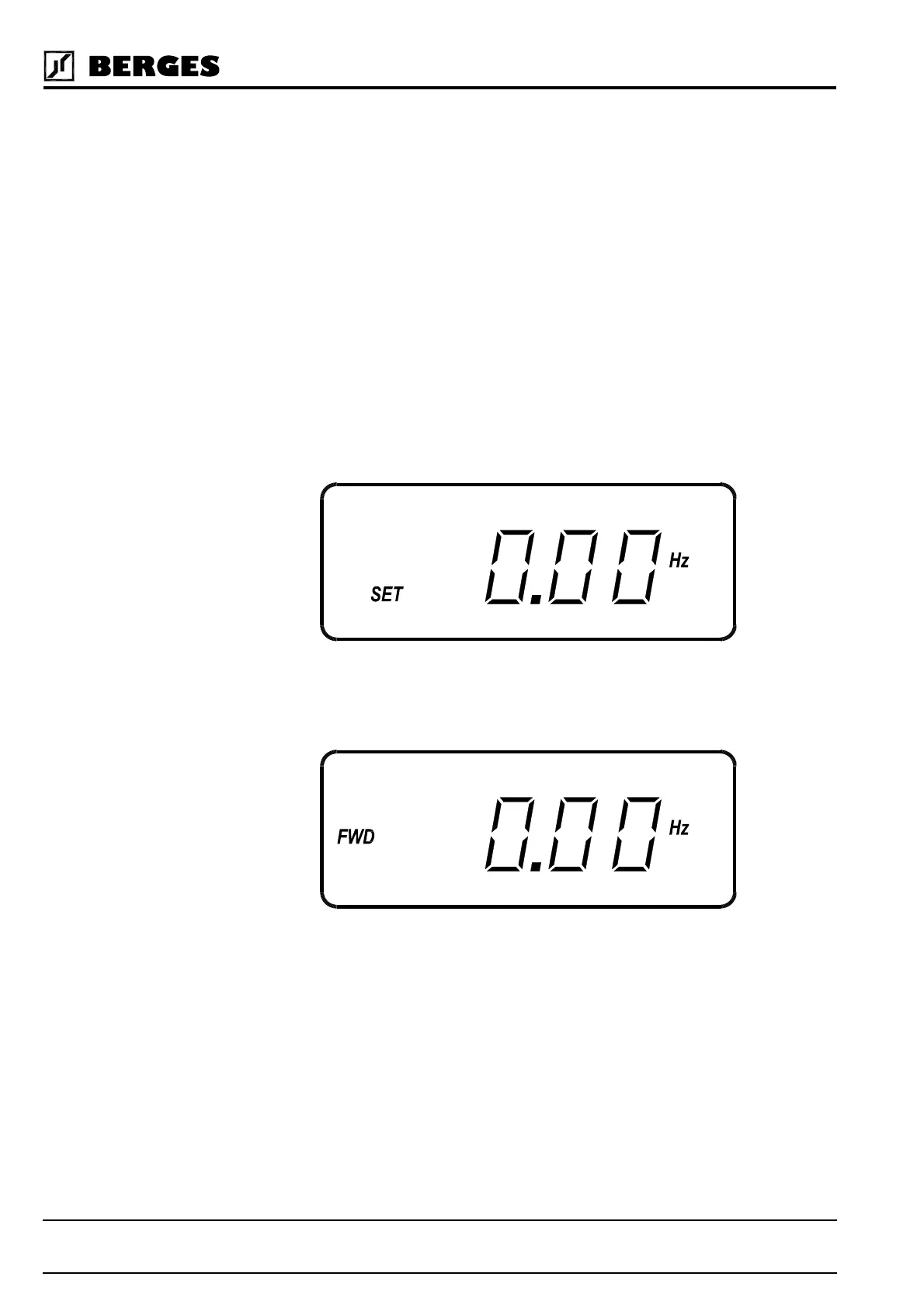
B. Apply AC power to the input terminals. For about two seconds the display will show all
segments active (see Figure 4.2). The STATUS indicator will then turn red (indicating a
Stop condition) and the display will change to:
C. The factory settings correspond to control via the analog input VIN1. Activate terminal
FWD or REV. The FWD and REV keys are thus ineffective. The display will e.g. change
to:
D. Control the VIN1 terminal with 0–5/10 V or 0/4–20 mA. When the display gets to 0.1 Hz,
the inverter will start to produce an output. The motor will already begin to run with a cor-
respondingly low load. When the motor starts to turn, check the rotation. If the motor is
turning in the wrong direction, PRESS STOP, REMOVE AC POWER AND WAIT FOR
ALL INDICATORS TO GO OUT. After the STATUS indicator has gone out, reverse any
two of the motor leads at M1, M2 or M3.
E. The inverter is preset to run a standard 4-pole AC induction motor to a maximum speed
of 50.00 Hz with both Acceleration and Deceleration times set to 3.0 seconds. See sec-
tion 9.1, “Parameter Code Summary” for a complete list of all factory settings.
Figure 4.3
Figure 4.4