Berges electronic • D–51709 Marienheide-Rodt • Tel. 02264/17-0 • Fax 02264/17126
Operating manual 21.12.98
ACP 3000 — 0.37–15.0 04_GB
58
7 Connection Diagrams
The following show some of the commonly used connections for operating the ACP 3000 from external devices. Refer
to section 3.15, page 27 for more information on the control input terminals.
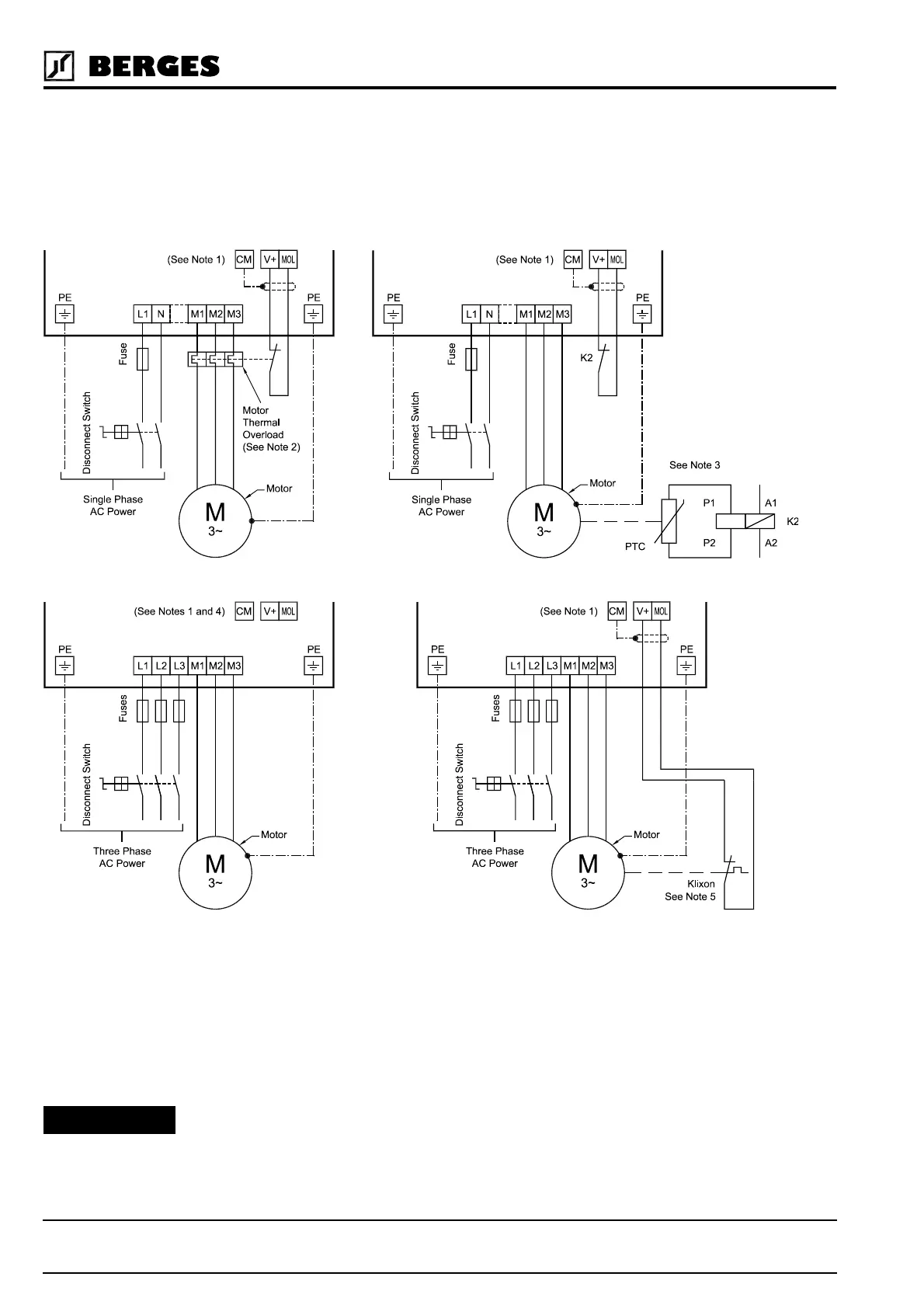
7.1 AC Line and Motor Connections (Mains supply 1 × 230 VAC and 3 × 400 VAC)
NOTES (FIGURES 7.1 UP TO 7.4):
1) See section 7.4, “Auxiliary Relay Output and Digital Output ST1” and 7.5, “MOL Terminal Connections” for other
connection schemes.
2) See parameter
67-TOL
.
3) Motor protection by external PTC evaluation.
4) Motor protection by means of the parameter
67-TOL
is recommended for single motor drives (STANDARD).
5) Motor protection by temperature switch (Klixon).
Frequency inverters must not be connected via a residual-current-op-
erated circuit-breaker as the sole protective measure! (refer to chapter
3.6, page 19)
Figure 7.1 Figure 7.2
Figure 7.3 Figure 7.4
ATTENTION!