21.12.98 Operating manual
04_GB ACP 3000 — 0.37–15.0
15
Berges electronic • D–51709 Marienheide-Rodt • Tel. 02264/17-0 • Fax 02264/17126
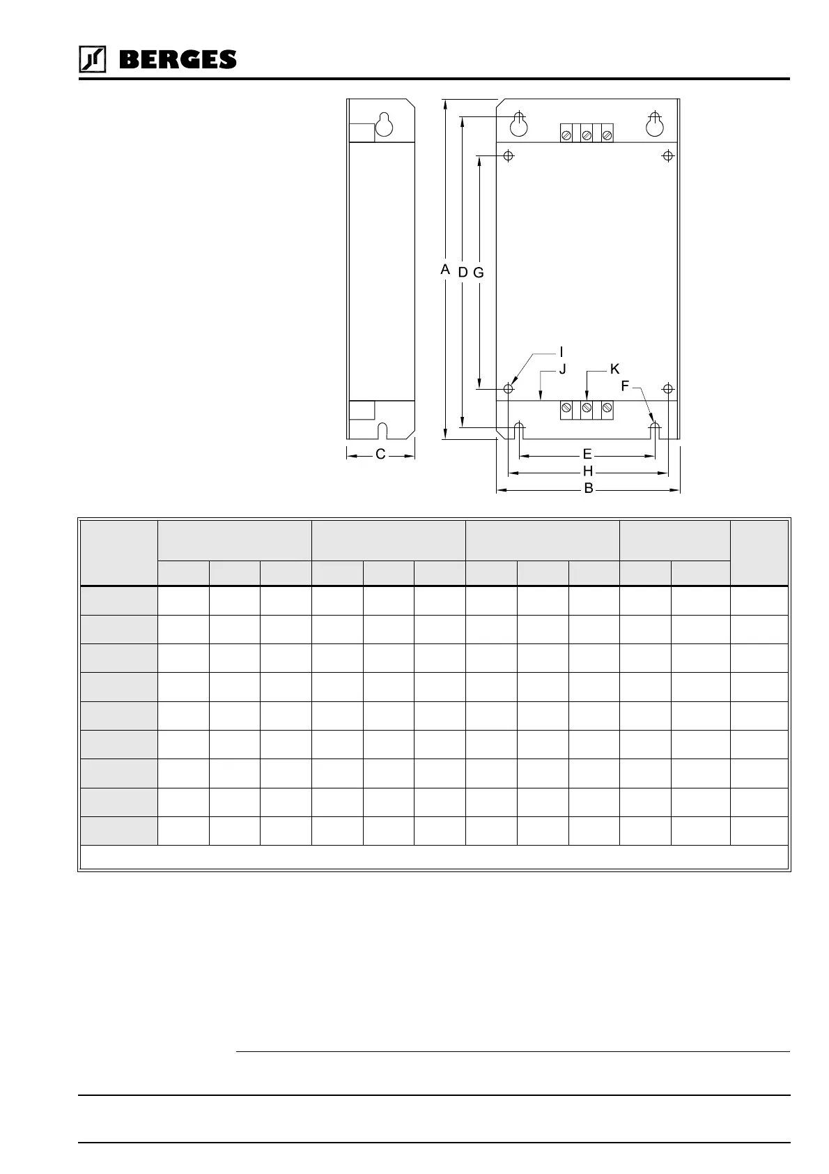
NOTE: Dimensions in mm.
(1)
3.3.4 Interference Suppression Measures
Electrical/electronic devices are capable of influencing or disturbing each other through
connecting cables or other metallic connections. “Electromagnetic compatibility” consists of
the factors “interference resistance” and “interference emission”. Correct installation of
the inverter in conjunction with any possible local interference suppression meas-
ures has a crucial effect on minimizing or suppressing mutual interference.
TYPE OUTER DIMENSIONS SECURING SECURING ON THE
INVERTER
CONNECTIONS FOOT-
PRINT
A B C D E F G H I J (PE) K
BE I 1005 200 108 40 183 80 M5 137 94 M5 M4
2,5 mm
2(1)
BE II 1010 200 145 40 183 110 M5 137 129 M5 M4
2,5 mm
2(1)
BE III 1020 250 145 45 235 110 M5 188 129 M5 M4
2,5 mm
2(1)
BE I 3003 200 108 40 183 80 M5 137 94 M5 M4
2,5 mm
2(1)
BE II 3005 200 145 40 183 110 M5 137 129 M5 M4
2,5 mm
2(1)
BE III 3012 250 145 45 235 110 M5 188 129 M5 M5
2,5 mm
2(1)
BE IV 3038 360 222 50 342 160 M6 280 200 M6 M5
16 mm
2(1)
BE V 3012 360 222 50 342 160 M6 280 200 M6 M5
16 mm
2(1)
BE VI 3040 496 232 50 478 180 M6 419 200 M6 M5
16 mm
2(1)
Table 3.2
(1) FOOTPRINT means that these filters have been prepared for the installation of an ACP converter on the filter (securing).