21.12.98 Operating manual
04_GB ACP 3000 — 0.37–15.0
55
Berges electronic • D–51709 Marienheide-Rodt • Tel. 02264/17-0 • Fax 02264/17126
B. Parameters Re-Defined for PI Control
This section describes amendments to existing parameters when the PI Controller is uti-
lized.
This parameter defines the source for speed reference and Run/Stop control input. The val-
ues shown below replace those given on page 36.
◊ Value range: 0–11 Default: 3
This parameter defines the speed setpoint selector. The values shown below are in addition
to those given on page 38.
NOTE:
DIRECT = Maximum output (
32-FMAX
) at maximum input.
INVERSE= Minimum output (
31-FMIN
) at maximum input.
◊ Value range: 0–19 Default: 0
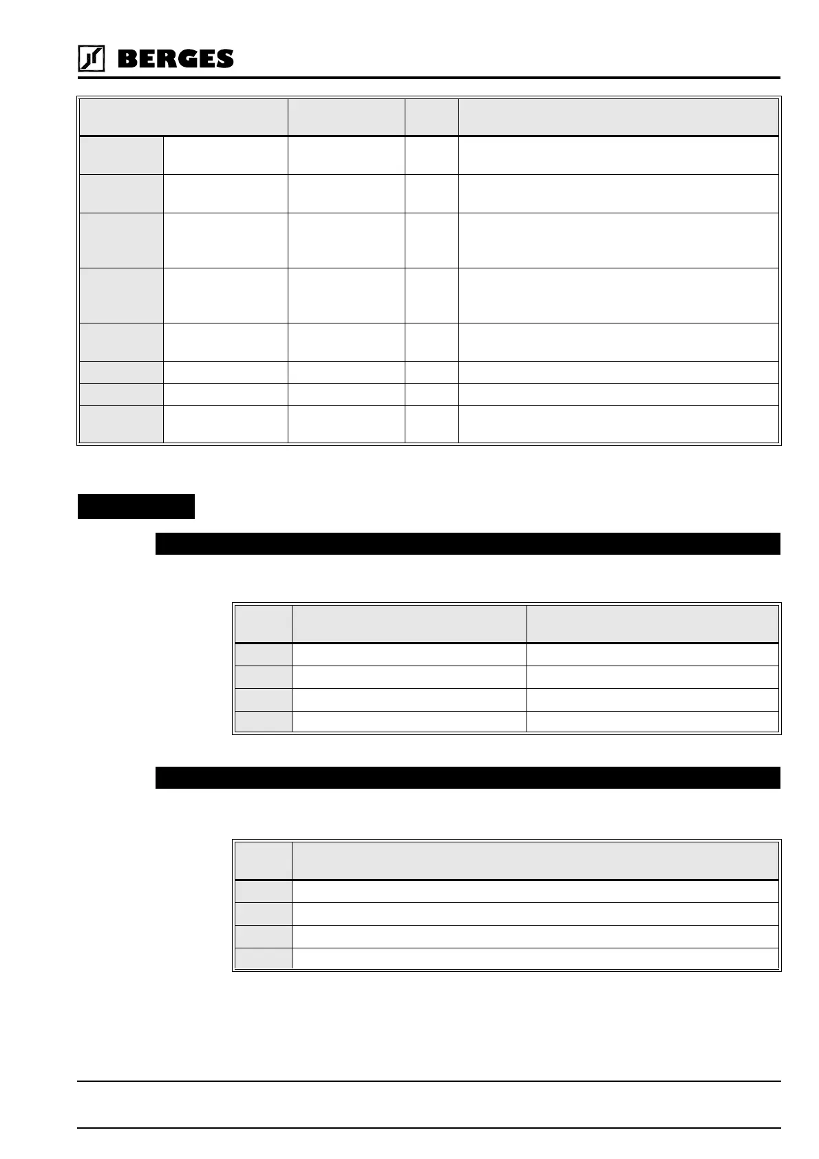
PARAMETER RANGE
OR UNITS
LEVEL DESCRIPTION
1A-FSTAT Stator Frequency – 2 Shows the stator frequency; the value may only be
read; it cannot be altered.
A1-FCORR Frequency
Correction
0.00–400.0 Hz 2 Used to limit the variation of the PI Regulator around
the value of parameter
12-FOUT
.
A6-ERROR2 Final Error – 2 This parameter is the Final Error of the PI Regulator.
It is calculated from PI output minus the value of
12-
FOUT
. The value may only be read.
A7-ERROR1 Initial Error – 2 This parameter is the Initial Error of the PI Regulator.
It is calculated from
12-FOUT
minus feedback. The
value may only be read.
A8-SIPART Integral Sum – 2 This parameter is the sum of the integral term of the
PI Regulator. The value may only be read.
B3-KP Proportional Gain 0–255 2 This parameter sets the proportional gain.
B4-KI Integral Gain 0–255 2 This parameter sets the integral gain.
B5-KIN VIN1 Scaling 0–255 2 This parameter sets the scaling for feedback termi-
nal VIN1.
21-MODE – Input Mode 1P
DATA
CODE
SPEED CONTROL SOURCE RUN/STOP CONTROL
0 Keypad Keypad (Forward only)
1 VIN2 Terminals Keypad (Forward only)
2 Keypad Terminals (2-wire maintained contact)
3 VIN2 Terminals Terminals (2-wire maintained contact)
24-FSEL – Speed Setpoint Selector 2P
DATA
CODE
DESCRIPTION
16 Both VIN1 and VIN2 are direct.
17 VIN1 is inverted and VIN2 is direct.
18 VIN1 is direct with a 20% offset and VIN2 is direct.
19 VIN1 is inverted with a 20% offset and VIN2 is direct.
HINT!