CA S/M CA L/XL
A
B
AB
A
B
AB
MANUAL INSTALLATION
Version: 6.1 (05-12-2011) 19
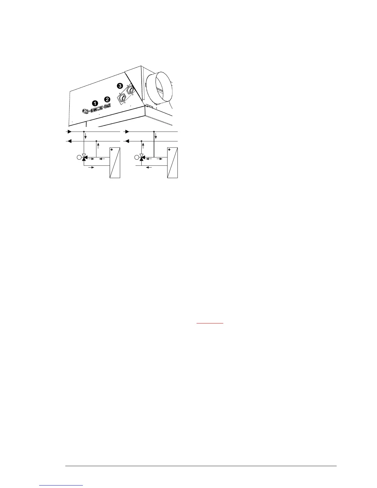
Units with side connection
On request, units with electrical 12 and water-side 3
con
nections on the side can be supplied. The water-side
control is then not built-in, but has to be connected outside
the unit during installation.
1. Connect the valve to the connections 3 as shown in the
diag
ram opposite.
2. Connect the valve drive to terminal 2.
2.5.2 Frost protection
The electronic control features integrated fr
ost protection. It
works in two stages:
1. If the discharge air temperature falls to below 5 ºC:
- the control panel will temporarily display fault message
E6
(see section 5.3);
- the valve of the integral water control will open fully;
- the output on the unit giv
es a signal for the central
heating installation (if function
61a/b. Function of output
1/2
on the operating panel is set to Frost protection).
2. If the discharge air temperature falls to below 2 ºC:
- fault message E6 will become final;
- the fans will be switched off, but the valve of the water
contr
ol will stay open.
The frost protection is automaticall
y lifted when the incoming
or outgoing air temperature rises to above 8 ºC.
Caution:
c The frost protection reduces the risk of freezing but does
not warrant 100% protection.
Take the following precautions if you install the unit in a
r
oom where frost may occur:
- Provide for constant circulation of the water at the
rig
ht temperature;
- Add up to 20% glycol to the water when the unit is not
in operati
on during the wintertime;
- Or drain the system and the unit (see section 6.8).
2.5.3 Connect the unit
1. Connect the unit to the central heating
system.