MANUAL INSTALLATION
Version: 6.1 (05-12-2011) 31
6. Using sheet metal screws, fix the discharge duct to the
angle sections 3.
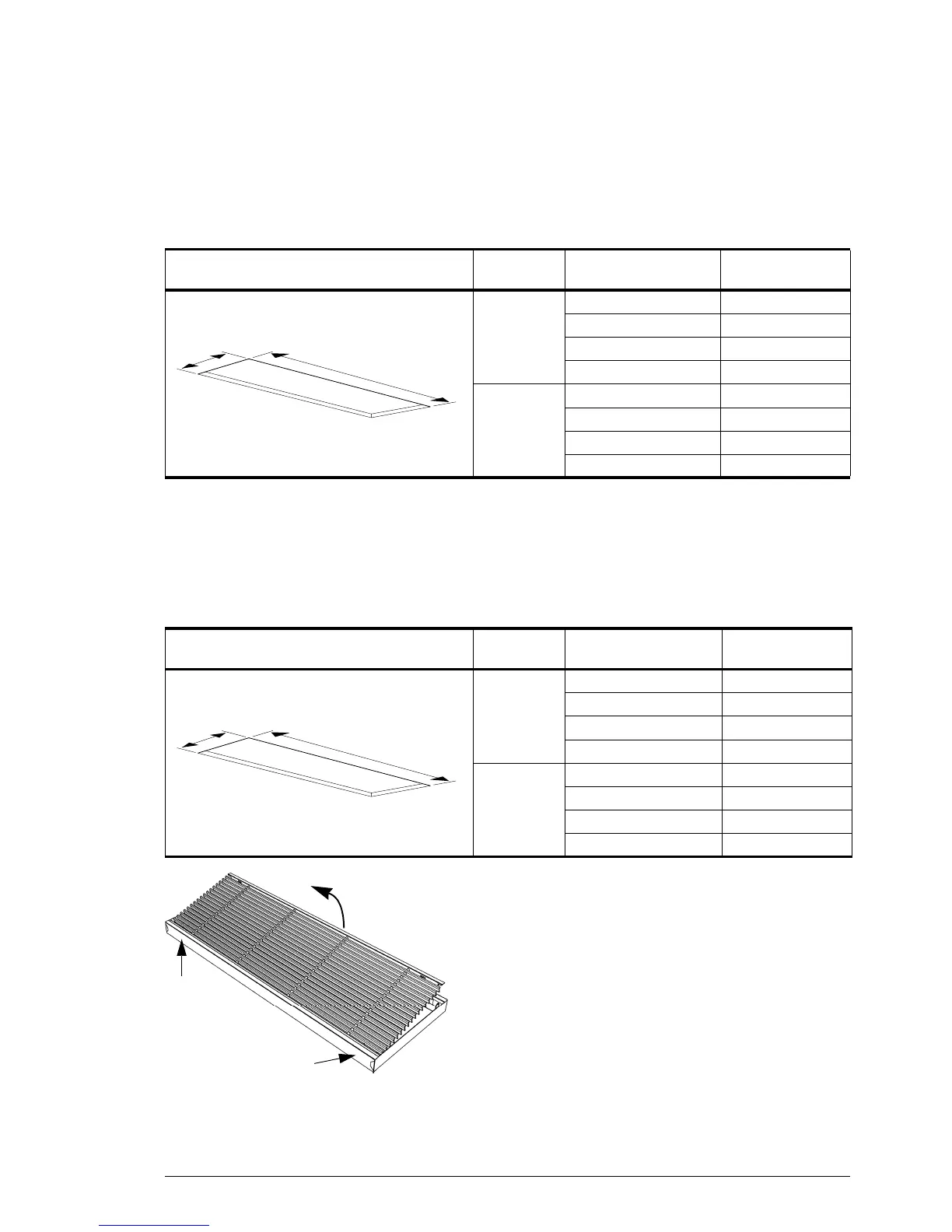
Installing the grille plenum of the inlet section
7. Make a hole in the false ceiling for the inlet section (see
T
able 2-4).
8. Take the inlet grille out of its frame:
- Push the two pins 1 in the grille towards one another
and ti
lt the grille outward.
- Push the two pins at 2 towards one another and take
t
he grille out.
Table 2-3 Dis
charge section hole dimensions
R
EFEREN
CE
TYPE DIMENSIONS
b
a
a CA
2
S-R 102 mm
CA
2
M-R 102 mm
CA
2
L-R 133,5 mm
CA
2
XL-R 133,5 mm
b CA
2
100-R 1008 mm
CA
2
150-R 1508 mm
CA
2
200-R 2008 mm
CA
2
250-R 2508 mm
Table 2-4 Inlet section hole dimensions
R
EFEREN
CE
TYPE DIMENSIONS
b
a
a CA
2
S-R 268 mm
CA
2
M-R 268 mm
CA
2
L-R 368 mm
CA
2
XL-R 368 mm
b CA
2
100-R 1008 mm
CA
2
150-R 1508 mm
CA
2
200-R 2008 mm
CA
2
250-R 2508 mm
1
1
2
2