INSTALLATION COMFORT AIR CURTAIN
24
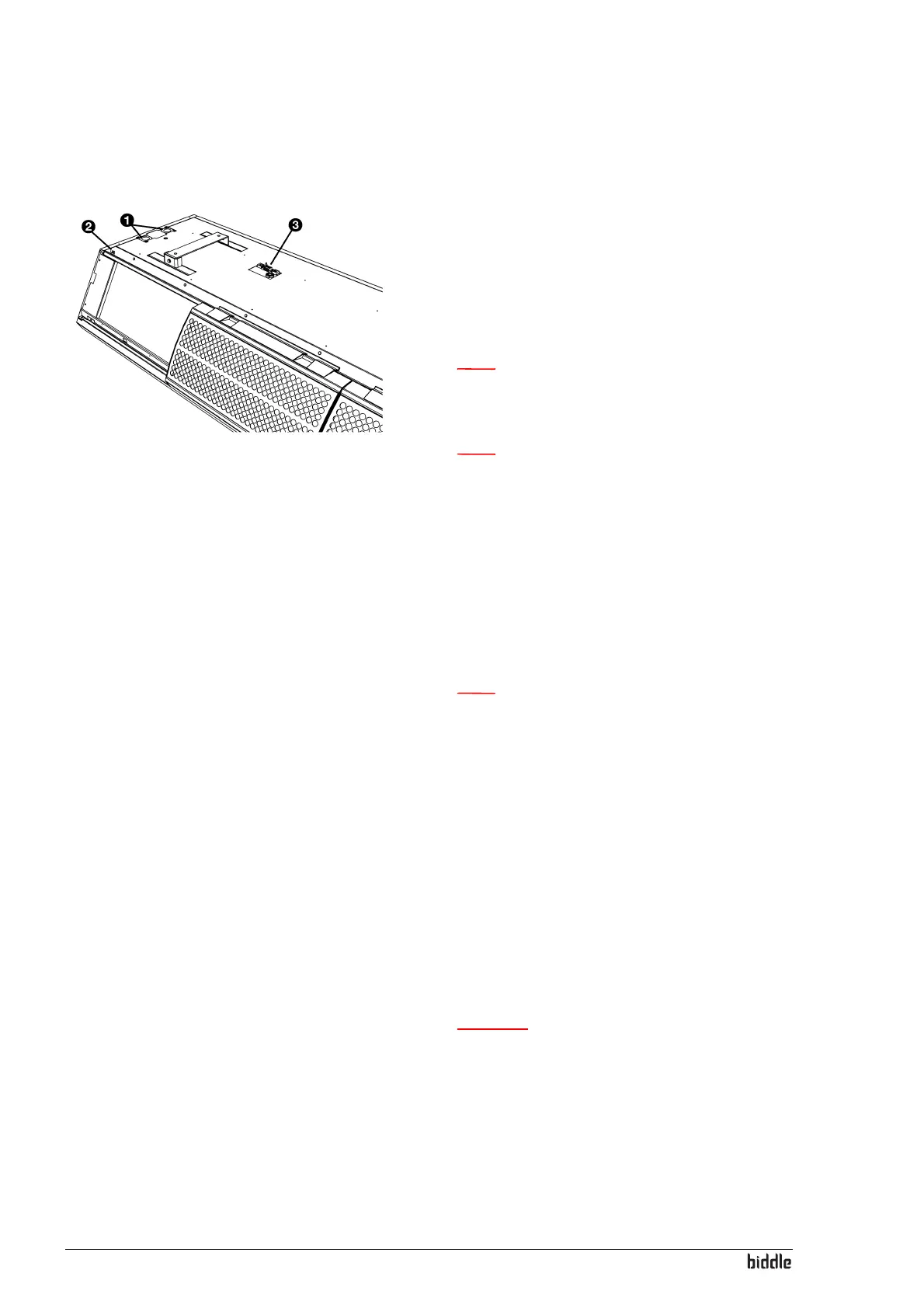
2.8.3 Connecting control panel to unit
The control panel connections G and E are located on the
connector plate 3 on the upper side of the unit. The two
sock
ets are identical. One of the two sockets has a dummy
plug.
1. Connect the control cable to the free terminal
G or E.
Note:
n Do not remove the dummy plug from the other
socket, as this may lead to faults.
Note:
n Leave approx. 30 cm of free cable length: It will be
needed to take the electronics out when servicing
the unit.
Multiple units operated from one control panel
1. For each unit to be linked, remove the dummy plug from
sock
et
G or E.
2. Link the units: Connect the control cables to
G and E.
Note:
n Do not remove the dummy plug from the last unit,
as this may lead to faults.
2.8.4 Connecting external controls (option)
The connector plate on the upper side of the unit has three
in
puts (X72) for the connection of external controls. The
inputs can be used to change the mode of operation of the
unit without the intervention of the user. The inputs can be
used for connection of e.g. a timer clock, a contact thermo-
stat or a GBS-controlled relay.
1. Connect the cable for the external controls (if used) to
the term
inals on the connector plate.
Caution:
c The input is designed for controls with potential free
contacts. Biddle recommends the use of components
with gold-plated contacts and a low resistance.
Preferably lower than 20 mΩ in order to be able to
switch 1 mA at 5 VDC.