CITY MANUAL INSTALLATION
Versie: 5.0 (04-06-2012) 25
2.8.5 Functions of the inputs
The functions of a control component depends on the termi-
nals to which the component is connected and on the settings
on the in
terface. The table below shows for each control func-
tion the terminals to which the control component has to be
co
nnected and how the interface has to be set.
The setting on the interface relates to the range of the con-
trol component:
• Loca
l: The control component is active on the unit to
which the component is connected
• Global: The contr
ol component is active not only on the
unit to which the component is connected, but also on all
other units connected to the same touch pad controller
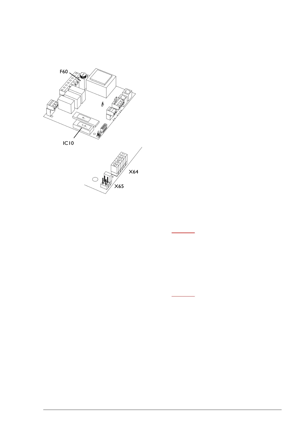
The range is set as standard to local. In order to set the con-
trol range to global, a jumper has to be moved on the inter-
face (block X64). The jumper to be moved depends on the
co
ntrol function (see table below). Place the removed jumper
in the reserve positions provided (X65).
The interface is located inside the unit and is accessible after
r
emoving the inspection panel.
Caution:
c For CITY:
A jumper is installed as standard between terminals
T and G. This jumper has to be removed if you
connect a control component to T and G. If you do
not install a control component, the jumper must be
left in place: The unit will not function without the
jumper.
Caution:
c For CYV:
CYV units are equipped with an release relay which
is controlled by the Daikin system. This relay is
connected to terminals T and G of block X72. The
unit can only be switched ON and OFF when the
Daikin system is active. If the Daikin system is not
active, the unit is OFF
You can choose to switch the unit ON and OFF
externally irrespective of the Daikin system. In this
case install a jumper or control component between
terminals T and G in place of or parallel to the
standard wiring.