9
Ø d
1
max
Ø d
4
h
2
Ø d
2
+0.1
0
Ø d
3
±0.2
h
1
+0.5
0
H max
Ø d
5
+0.2
+0.1
K
+0.4
0
W
D10
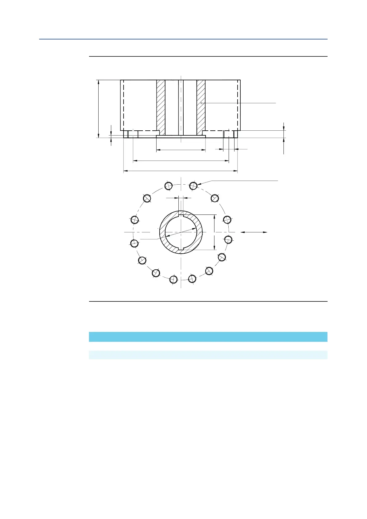
50 800 315 698 M36 24 10 32 430 240 56 264.8
60 840 315 698 M36 24 10 32 430 240 56 264.8
MAN 604A Rev. 5
Installation
Section 2: Installation
Dimensions in millimetersw
Actuator model Ø d
1
Ø d
2
Ø d
3
Ø d
4
N h
1
h
2
H max Ø d
5
W K
Figure 6
Drive sleeve
N. THREADED HOLES
Top view of the scotch yoke mechanism
(actuator shown in closed position)
Flow line
Installation, Operation and Maintenance Manual
June 2020
Table 6.