11
Ø d
1
max
Ø d
4
h
2
Ø d
2
+0.1
0
Ø d
3
±0.2
h
1
+0.5
0
H max
Ø d
5
+0.2
+0.1
K
+0.4
0
W
D10
100 1200 450 1042 M42 32 8 57 600 300 70 328.8
MAN 604A Rev. 5
Installation
Section 2: Installation
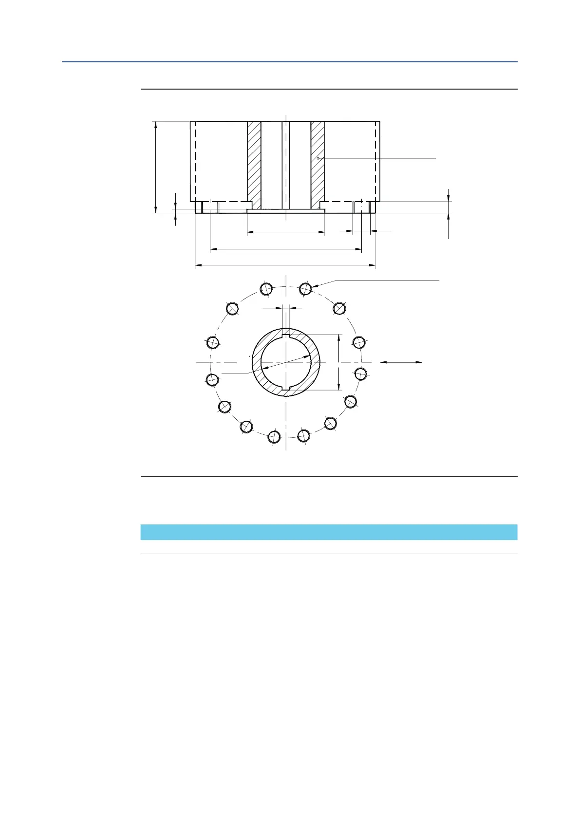
Dimensions in millimeters
Actuator model Ø d
1
Ø d
2
Ø d
3
Ø d
4
N h
1
h
2
H max Ø d
5
W K
Figure 8
Drive sleeve
N. THREADED HOLES
PCD, holes, number and size
according to ISO 5211
(but the holes are on centerline
instead of straddle the centerline)
Top view of the scotch yoke mechanism
(actuator shown in closed position)
Flow line
Installation, Operation and Maintenance Manual
June 2020
Table 8.