12
MAN 604A Rev. 5
Installation
Section 2: Installation
If required, for the standard models size 0.3 to 6, Bif can supply an insert bush with
unmachined bore in accordance with Bif standard table SCN6202. On request the insert
bush bore can be machined by Bif to couple the valve stem, provided its dimensions
match the maximum stem acceptance of the bush according to Bif table TN1005,
enclosed. The particular execution of the ange and bushing allow the actuator to
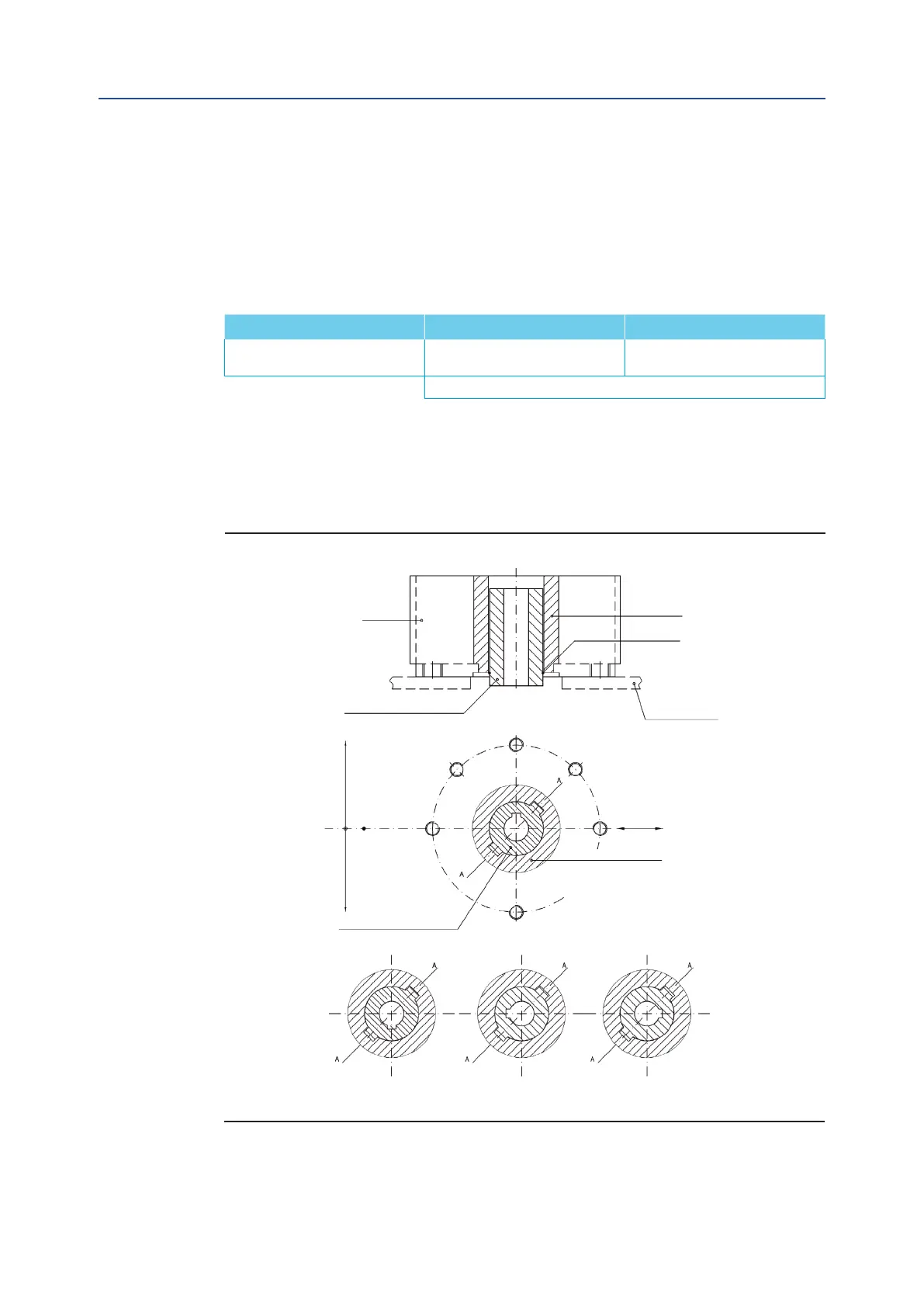
be rotated by 90° in 4 different positions according to the Figure 9.
The Bif insert bush with 2 external keys at 45° allows to position the keyway for the valve
every 90°. Consequently actuator can be mounted in 4 positions at 90° on top of the valve.
For biggest actuator models, the bore of the yoke can be machined according to the
dimensions of valve stem.
Flow line
N.4 holes ange
N.8 holes ange
Drive sleeve
Snap ring
Housing
Insert bush
Insert bush
Adaptor ange
Drive sleeve
Standard position 1
Position 2 Position 3 Position 4
Position 2 Position 3 Position 4
Rotate insert-bush 180° around
vertical-standard position (1)
Rotate insert-bush 180° around
axis A-A, from position (2)
Rotate insert-bush 180° around
axis A-A, from position (1)
Insert bush turned upside down
Figure 9 Insert bush + intermediate coupling ange
June 2020
Installation, Operation and Maintenance Manual
Table 9.