14
BIFFI FAIL SAFE ELECTRIC ACTUATORS, MODEL EFS2000V4
InstructIon and operatIng Manual
8.3 Locking the 3-position selector
The 3-position selector can be locked in any
ofits three positions by means of a padlock.
8.4 Remote control
Place the 3-position selector in REMOTE to
transfer the actuator control to a remote
control system. Local OPEN or CLOSE
operation will be inhibited. Only the local
STOP control remains active. Using the
“VIEW and SET-UP” features may configure
different control modes. The remote controls
are opto-coupled. A non-regulated 24V DC
voltage (variable from 23 to 27V DC, max. 4W)
is available on the actuator terminal board to
supply the remote controls or external devices.
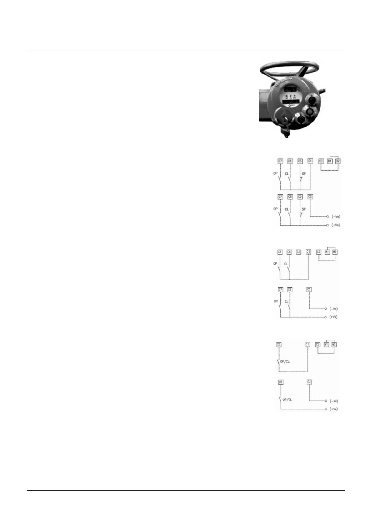
8.4.1 Remote commands
For EFS standard version
Using the “VIEW and SET-UP” features may
configure different control modes.
Four wires (see the remote connections
diagram shown).
In “4 wires latched” (OPEN, CLOSE, STOP,
COMMON) mode, with the OPEN or CLOSE
signal switched to ON, the motor is energized,
and it continue to run after the signal returns to
OFF. To stop the motor, press STOP. To reverse
the direction, press STOP and then press the
button relevant to the opposite direction. The
action of the STOP signal (stop with signal ON
or stop with signal OFF) may be reversed using
the VIEW and SET-UP features, see chapter
‘set-up routines, paragraph ‘remote controls’.
Three wires (see the remote connections
diagram shown).
With option “3 wires” (OPEN, CLOSE,
COMMON), the actuator can be driven in either
“push-to-run” or “latched with instant reverse”
mode. In “push-to-run” mode, the actuator can
be driven to the desired position by switching
the OPEN or CLOSE signal to ON. As the signal
returns to OFF, the motor is de-energized. In
“latched with instant reverse” mode, when the
OPEN or CLOSE signal switches to ON, the
motor is energized, and it continues to run after
the signal returns to OFF. If the signal relevant
to the opposite direction is activated, the
actuator reverses its direction and maintains
the new direction also if the signal returns
toOFF.
The circuits associated to the inputs are
opto-coupled and be supplied by the internally
generated 24V DC or by an external 20-125V
DC or 20-120V AC (50/60Hz) power supply. The
signal levels are the following:
• Minimum ON signal > 20V DC or 20V AC
(50/60Hz)
• Maximum ON signal < 125V DC or 120V AC
(50/60Hz)
• Maximum OFF signal < 3V
• Minimum signal duration > 500 ms.
• Total current drawn from remote controls
<25 mA
Two wires (see the remote connections
diagram shown).
With the “2 wires” option, 2 different activities
may be selected: In “2 wires, signal ON to
open”, the actuator opens if the signal switches
to ON and closes if the signal goes to OFF.
In “2wires, signal ON to close”, the actuator
closes if the signal switches to ON and opens if
the signal switches to OFF. This option requires
two wires (signal and common).
Option A1)
Option B1)
Option A2)
Option B2)
Three wires (INT/EXT powered)
Option A3)
Option B3)
Two wires (INT/EXT powered)
Four wires (INT/EXT powered)