9
BIFFI FAIL SAFE ELECTRIC ACTUATORS, MODEL EFS2000V4
InstructIon and operatIng Manual
7 EFS OPERATION
7.1 Operating the EFS 2000v4 for the first time
Before connecting electrical power to the
actuator and ESD clutch, check that the
voltages are correct. The ESD clutch can be
operated by any voltage in the range of 24V
DC-240V AC. The power to the actuator should
be supplied according to the indication on
the nameplate. Wrong power supply could
cause permanent damage to the electrical
components. Check of phase rotation is not
necessary since the unit is provided with
automatic phase rotation correction. Check
that the valve is in SAFE POSITION and the
manual override selector is in AUTO. Place the
3-position selector in OFF and apply power to
the actuator and ESD clutch. The alphanumeric
display of the actuator shows the following
message for about 3 seconds:
Then the new message should be:
or
according to the configuration present in
the memory. If the upper line of the display
shows “ALARM”, remove the alarm before
proceeding (see chapters ‘maintenance’ and
‘trouble-shooting’). If the upper line of the
display shows “WARNING”, a warning condition
is present. You can continue if the EFS2000 is
working okay, but some data is not according
to the configured parameters (see chapters
‘maintenance’ and ‘trouble-shooting’). If
the upper line of the display shows “INT”,
an interlock input is active. If the upper line
of the display shows “INT EFS”, the clutch
is not energized and the actuator cannot be
electrically operated. If the upper line of the
display shows “NORMAL” the actuator can
beelectrically operated.
Biffi Italia
EFS2000 v4 ntb
INT EFS OFF
STOP
INT EFS OFF
R%: xxx.x
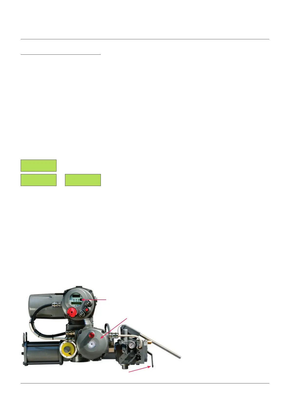
Red/green LED
Red/green LED
Actuator display
Do not operate the actuator without first
checking that the configuration is according
to the required application by using the “VIEW
and SET-UP” features (see chapters ‘view
menu’, ‘setup menu’, ‘view routines’ and
‘setup routines’). In particular the following
parameters have to be set:
• ICON power-fail: enabled or disabled
• Selector in OFF: enabled or disabled
• Autoreset: enabled or disabled
• Reset delay: from 1 to 255 sec. The
recommended value is greater than 1.5 times
the maximum valve stroke time during EFS
action.
The ESD clutch can not be energized until the
manual override selector is in MANUAL.
If AUTORESET was configured “enabled”,
wait until the LED in the clutch enclosure is
green and the INT EFS message on the local
display disappears. Place the local selector in
LOCAL and electrically drive the actuator to
open and close. If AUTORESET was configured
“disabled”, wait until the LED in the clutch
enclosure is red and then push the red
mushroom push button. When the above LED
is green, the INT EFS message on local display
disappears. Place the actuator local selector
in LOCAL and electrically drive the actuator
to open and close by means of the OPEN/YES
and CLOSE/NO push button. Set torque limits
and position limits by means of the “stroke
limits routine” in the “actuator set-up” menu.
When the stroke limits and the configurations
are correct, move the 3-position selector to
LOCAL and drive the actuator to either open or
closed position. Move the 3-position selector to
REMOTE, to remotely control the actuator.