7
BIFFI FAIL SAFE ELECTRIC ACTUATORS, MODEL EFS2000V4
InstructIon and operatIng Manual
6 INSTALLATION
6.1 Working condition
The standard EFS2000v4 are suitable for the
following ambient temperatures:
from -20°C to +70°C (from -22°F to +158°F) or
from -45°C to +70°C (from -49°F to +158°F)
IMPORTANT
Check the “temperature ambient range”
embossed on the nameplate, for the correct
utilisation with respect to the ambient
temperature.
Installation in ambient with temperature range
outside the specified values will invalidate the
warranty.
6.2 Removing the electrical enclosures covers
In the EFS2000v4 is foreseen the terminal
enclosure shown in the following Picture.
Using an Allen key, loosen the four screws
fixing the cover and then remove it.
WARNING!
Pay attention to do not damage the joint surface
of the covers.
IMPORTANT
In case the screws of the cover must been
replaced, a SS AISI 316Class A4 must be used
with minimum yield strength of 450 N/mm
2
.
Main terminal enclosure for power
and control wires
6.3 Electrical connections
Before applying power to the EFS2000v4 check
that the electrical parameters (supply voltage
and current) shown on the nameplate and on
the attached wiring diagram, are correct for the
installation.
IMPORTANT
All the accessories required for the EFS2000v4,
in particular the cable glands, must be certified
according to the Standard Directive and specific
rules, which apply for the specific application.
Remove the plugs from the cable entries.
For electrical connections use components
(cable glands, cables, hoses, conduits) which
meet the requirements and the applicable
codes of the plant specifications (mechanical
protection and/or explosionproof protection).
Screw the cable glands (or the conduits) tightly
into the threaded entries, in order to guarantee
a weatherproof and explosionproof protection
(when applicable).
Insert the connection cables into the electrical
enclosure through the cable glands (or
conduits) and connect the power supply,
the control, the signal and ESD wires to the
actuator, by linking them with the terminal
blocks termination as per the wiring diagram.
Replace the plastic plugs of the unused
cable entries by metal ones, to guarantee
perfect weatherproof tightness and to comply
with the explosionproof protection codes
(whereapplicable).
Once the connections are completed, check
that the controls and signals work properly.
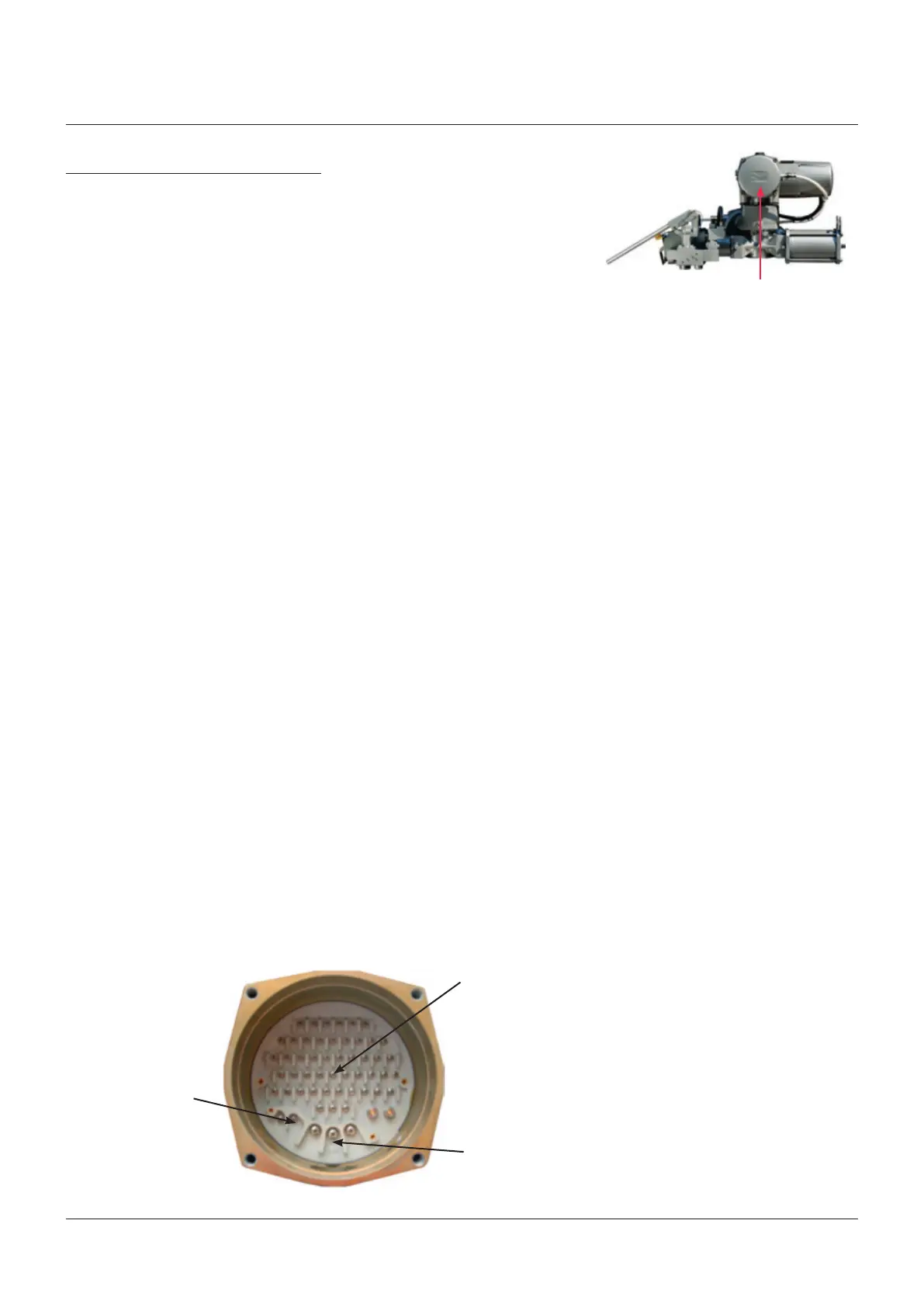
Terminals for remote
control
Terminals to electrical
power of actuator
Terminals to
electrical power
of ESD clutch
Main terminal board
6.4 Cable entries
The sealing of cable and conduit entry should
be carried out in accordance with national
standards or the regulatory authorities
that have certified the EFS2000v4. This is
particularly the case for units that are certified
for use in hazardous areas where the method
of sealing must be to an approved standard
and cable glands, reducers, plugs and adapters
must be approved and separately certified.
IMPORTANT
• To prevent water ingress through the cable
conduits, verify that the cable glands used have
the minimum degree of protection required by
the plant.
• If rigid conduits are used, it is suggested to
place a flexible pipe connection between the
conduit and the terminal board.
Remove the cable entry plug.
To guarantee weatherproof and explosionproof
operation, screw the cable glands tightly (at
least 5 turns) and block it with a thread sealant.
The use of a thread sealant is necessary in case
of explosionproof conditions.
If some parts of the cable glands have been
removed during work on the cable entries put
them back into place in order to avoid losing
the dismantled parts.