4
L
O
P
C
F
F
O
R
E
M
O
T
E
L
O
C
A
L
BIFFI FAIL SAFE ELECTRIC ACTUATORS, MODEL EFS2000V4
InstructIon and operatIng Manual
3 STORAGE AND PRE-INSTALLATION
IMPORTANT
Omitting the following procedures will invalidate
the product warranty.
3.1 Checks to be carried out on receipt of the
actuator
• Check first of all if the information written
on the nameplate (models, nominal torque,
nominal voltage, degree of protection, etc.)
corresponds with the data of the product
which is expected.
• If the actuator arrives already assembled onto
the valve, the configuration of the mechanical
stops and of the electric end of travel has
already been made by the person who
assembled the actuator onto the valve.
• If the actuator arrives separately from the
valve, the configuration of the mechanical
stops and of the electric end of travel must be
checked and, if necessary, carried out while
assembling the actuator onto the valve.
• Check that the actuator has not been
damaged during transport. If necessary,
repair all damages to the paint-coat, etc.
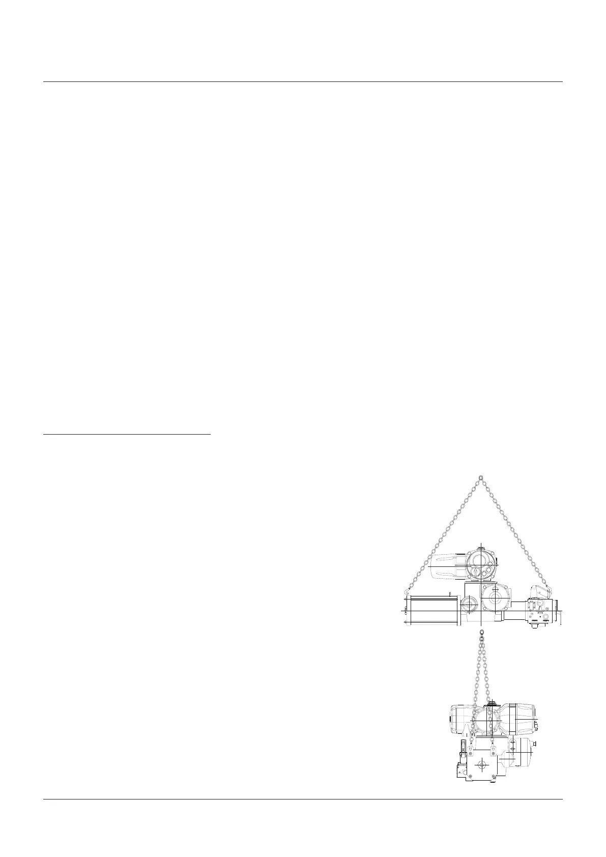
Actuator’s lifting points
• Check that the model, the serial number
of the actuator and the performance data
written on the data-plate correspond
with those described on the order
acknowledgement, test certificate and
delivery note.
• Check that the fitted accessories
correspond with those listed in the order
acknowledgement and the delivery note.
3.2 Actuator handling
IMPORTANT
The lifting and handling should be made by
qualified staff and in compliance with the laws
andprovisions in force.
WARNING!
The fastening points are appropriate for the
lifting of the actuator alone and not for the
valve+actuator assembly. Avoid that during the
handling, the actuator passes above the staff.
The actuator should be handled with appropriate
lifting means. The weight of the actuator is
reported on the delivery bill.
3.3 Storage procedure
The actuators leave the factory in an excellent
working condition and with an excellent
finish (these conditions are guaranteed by
an individual inspection certificate); in order
to maintain these characteristics until the
actuator is installed on the plant, it is necessary
to observe a few rules and take appropriate
measures during the storage period.
• Make sure that plugs are fitted in the air
connections and in the cable entries. The
plastic plugs which close the inlets do not
have a weatherproof function, but are only
a means of protection against the entry of
foreign matter during transport. If long-term
storage is necessary and especially if the
storage is outdoor, the plastic protection
plugs must be replaced by metal plugs,
which guarantee a complete weatherproof
protection.
Input shaft of the epicyclical gearing reduction
is connected the multi-turn actuator output
shaft; output shaft of the epicyclical gearing
reduction is connected to the pinion of rack-
pinion mechanism. The female wheel of the
epicyclical reduction is reversible: during
normal operation it is kept on position by
means of a electromagnetic clutch which hold
the worm shaft connected to the epicyclical
gearing.
The coil of the electromagnetic clutch is
normally fed by a direct current from separated
external power source, or derived from motor
power voltage, through a supply module.
When the ESD condition occurs, the supply to
the electromagnetic clutch is cut causing the
disconnection of system which hold the worm
shaft: in this conditions the epicyclical gearing
become reversible causing the movement of
the actuator on the fail condition by the effect
of the spring. To avoid dangerous shock to
the valve during the ESD action, an hydraulic
damper is mounted on the spring system, with
an adjustable flow control orifice to be set to
obtain the specified ESD times.
Position of the valve is continuously monitored
both in electric mode, both in fail-safe
condition, by means of a position sensor
directly connected the EFS2000v4 output drive.