3
BIFFI FAIL SAFE ELECTRIC ACTUATORS, MODEL EFS2000V4
InstructIon and operatIng Manual
2 DEVICE DESCRIPTION
2.1 General
The EFS2000v4 (Electric Fail Safe) is an electric
quarter turn spring return actuator which has
the purpose to move the valve in a "fail safe"
state (Fail Open or Fail Close), when the system
is de-energized.
As it's described in the next sections, several
modes for EFS2000v4 are available in order
to move the valve in a "fail safe" state but it's
important to highlight that the "safety function"
with SIL classification is only the one mentioned
in the document:
- SM 020 (SIL Safety Manual – Actuator
series EFS2000 v4) which clearly defines the
EFS2000v4 "safety function" as follow:
"The actuator performs the safety function on
demand if it delivers a full stroke driven by the
spring, moving the valve to the safe position
(either closed or open depending upon the
valve to be actuated) when the system is de-
energized (i.e. cutting the electric supply to the
electromagnetic clutch)."
Statement above clearly specify mode of
operating the actuator in order to perform the
"safety function" (i.e. cutting the electric supply
to the electromagnetic clutch).
Note: in the next section of present IOM, only
"safety function" (as it's defined here above) will
be considered as an action related to an ESD
(Emergency Shut-Down) command.
Any other device described in the next sections
of present Instructions and Operating Manual
which commands the actuator to reach its fail
safe state shall not be considered as "Safety
Functions".
All these device are not compliant to IEC
61508 requirements, they are not a safety
system and they are not SIL classified.
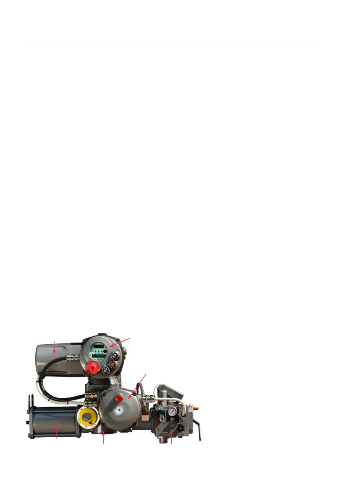
Multi turn electric actuator
Local control and configuration panel
Spring return mechanism
Epicyclic gear reduction
Hydraulic control group
Electro-mgnetic clutch
All actions of Shut-Down related to these type
of commands or device shall not be considered
in an Emergency Condition
Note: in order to avoid misunderstanding, in
the next section of present IOM, acronym ESD
without any explanation has to be intended with
the meaning of Emergency Shut-Down. Where
it's specified, acronym ESD has to be intended
as EFS shutdown.
The PST (Partial Stroke Test) functionality is
also available integrated in the actuator control
system in order to check the integrity of the
actuator and valve in safety applications. In
many cases, however, there was difficulty to
find out on site the pneumatic/hydraulic power,
while the electric power supply is always
available in every industrial plant.
2.2 Main parts description
The EFS2000v4 actuator consists of six main
parts:
• A spring return mechanism, which moves
the valve in the predefined fail-safe condition
when requested by an esd signal or by a
power failure.
• A multi-turn electric actuator which operates,
through an epicyclical gearing, the valve
during normal working conditions and at the
same time compresses the spring when the
operation is opposite to the fail safe direction.
• An epicyclical gear reduction to increase the
torque of the multi turn actuator.
• An electro-magnetic clutch to keep the
epicyclical gearing in position during normal
operation and release it in case of fail-safe
function.
• A hydraulic control group to adjust
the fail-safe speed and to manually
operate the actuator by means of an
hand-pump in case of power failure.
2.3 Operating principle
The spring return system is kept in fail safe
position by helical springs. During the normal
operation the multi-turn turn electric actuator
transmits the movement to the valve through
the epicyclical gearing reduction and to the
spring return mechanism through the rack.
Spring return mechanism is based on rack-
pinion mechanism; the rack is connected in
one side to the spring and in the other side to
the hydraulic cylinder; pinion of rack-pinion
mechanism is connected to the valve stem.
To prevent potential damages a manually
operated switch interrupts the automatic
operation during themanual operation
by a hand-pump.
• A local control and configuration panel, which
is used to configure the parameters and to
operate locally via OPENCLOSE-STOP push-
buttons and 3-position LOCAL-OFF-REMOTE
selector the actuator when electric power is
present.