EasyManua.ls Logo

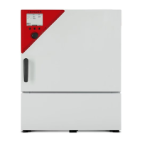
Binder KB 115 (E4) User Manual

Default Icon
149 pages
To Next Page IconTo Next Page
Page #1 background imageLoading...
Page #1 background image
Issue 02/2017 Art. No. 7001-0307
Operating Manual
Translation of the original operating manual
KB (E4), KB (E6)
Cooling Incubators
with compressor technology and program control
Model Model version Art. No.
KB 53 (E4) KB053-230V 9020-0199, 9120-0199
KB 53-UL (E4) KB053UL-120V 9020-0302, 9120-0302
KB 115 (E4) KB115-230V 9020-0397, 9120-0397
KB 115-UL (E4) KB115UL-120V 9020-0398, 9120-0398
KB 240 (E6) KB240-230V 9020-0202, 9120-0202
KB 240-UL (E6) KB240UL-120V 9020-0304, 9120-0304
KB 400 (E6) KB400-230V 9020-0203, 9120-0203
KB 400-UL (E6) KB400UL-120V 9020-0305, 9120-0305
KB 720 (E6) KB720-230V 9020-0204, 9120-0204
KB 720-UL (E6) KB720UL-240V 9020-0306, 9120-0306
BINDER GmbH
Address Post office box 102
78502 Tuttlingen, Germany
Tel. +49 7462 2005 0
Fax +49 7462 2005 100
Internet http://www.binder-world.com
E-mail info@binder-world.com
Service Hotline +49 7462 2005 555
Service Fax +49 7462 2005 93 555
Service E-Mail service@binder-world.com
Service Hotline USA +1 866 885 9794 or +1 631 224 4340 x3
Service Hotline Asia Pacific +852 390 705 04 or +852 390 705 03
Service Hotline Russia and CIS +7 495 98815 16

Table of Contents

Questions and Answers:

Binder KB 115 (E4) Specifications

General IconGeneral
BrandBinder
ModelKB 115 (E4)
CategoryAccessories
LanguageEnglish

Summary

1. SAFETY

1.5 General Installation & Operation Safety

Provides essential safety guidelines for installation and operation.

1.6 Intended Use

Specifies the intended applications and limitations of the cooling incubators.

1.8 Accident Prevention Measures

Outlines safety measures implemented by the manufacturer to prevent accidents.

3. DELIVERY, TRANSPORT, STORAGE & INSTALLATION

3.4 Installation Site and Ambient Conditions

Specifies requirements for the installation site and environmental conditions.

4. EQUIPMENT INSTALLATION

4.3 Electrical Connection Procedures

Explains how to connect the chamber to the power supply, including voltage and fuse details.

5. START UP PROCEDURE

6. T4.12 CONTROLLER FUNCTION OVERVIEW

6.2 Operating Modes Explanation

Explains different operational states like 'control off' and 'fixed value'.

7. OPTIONAL EQUIPMENT CONFIGURATION

8. FIXED VALUE SET-POINT ENTRY

8.2 Quick Menu Set-Point Entry

Steps to input set-points using the quick menu function.

8.3 General Menu Set-Point Entry

Steps to input set-points using the general menu.

9. TIME PROGRAMS

9.1 Start and Run Time Program

How to start and execute a pre-programmed time sequence.

9.2 Cancel Running Time Program

Procedure for stopping an active time program.

9.3 Create New Time Program

Detailed steps for creating custom time-based temperature programs.

10. WEEK PROGRAMS

10.1 Start and Run Week Program

How to initiate and run a pre-defined weekly program.

10.2 Cancel Running Week Program

Procedure for stopping an active weekly program.

10.3 Create New Week Program

Guide to setting up custom programs for weekly operation cycles.

11. KEY LOCK FUNCTIONALITY

11.3 Change Password for Key Lock

Procedure for modifying the password to access the controller.

12. GENERAL CONTROLLER SETTINGS

12.7 Factory Reset Procedure

Restoring the controller configuration to its original factory settings.

12.8 Network Configuration Settings

Setting up network parameters for chamber communication.

13. USB DATA TRANSFER

14. NOTIFICATIONS AND ALARMS

14.2 Alarms Overview

Overview of alarm messages, their causes, and corresponding icons.

14.4 Confirming a 'Set' Alarm

Procedure to acknowledge and reset an active alarm condition.

15. EVENT LIST

16. MEASURED VALUES GRAPHICAL DISPLAY

17. TEMPERATURE SAFETY DEVICES

17.1 Over-temperature Protective Device (Class 1)

Describes the primary safety device that permanently shuts off the chamber.

17.2 Overtemperature Safety Controller (Class 3.1)

Explains the electronic safety controller for overtemperature protection.

17.2.1 Safety Controller Modes

Details the 'Limit' and 'Offset' modes for the safety controller.

17.2.2 Setting the Safety Controller

Procedure for configuring the safety controller's mode and set-point.

17.3 Over/Undertemperature Safety Controller (Class 3.3)

Information on the optional combined over/undertemperature safety controller.

17.3.1 Safety Controller Modes (Class 3.3)

Explains 'Limit' and 'Offset' modes for the class 3.3 safety controller.

17.3.2 Setting Over/Undertemperature Controller

How to set up the over- and undertemperature safety controller.

18. DEFROSTING DURING REFRIGERATION

20. MAINTENANCE, CLEANING, AND SERVICE

20.1 Maintenance and Service Intervals

Guidelines for regular maintenance and service requirements.

20.2 Cleaning and Decontamination

Procedures for cleaning and decontaminating the chamber.

21. DISPOSAL PROCEDURES

22. TROUBLESHOOTING GUIDE

23.5 Equipment and Options Overview

23.6 Spare Parts and Accessories

26. CONTAMINATION CLEARANCE CERTIFICATE

Related product manuals