Bird SiteHawk Operation Manual
19
11. Place a marker (mark 2) at the maximum loss point within the frequency
band on the trace.
12. Save and label the trace, if appropriate. See
“Recall Trace Data” on
page 42
.
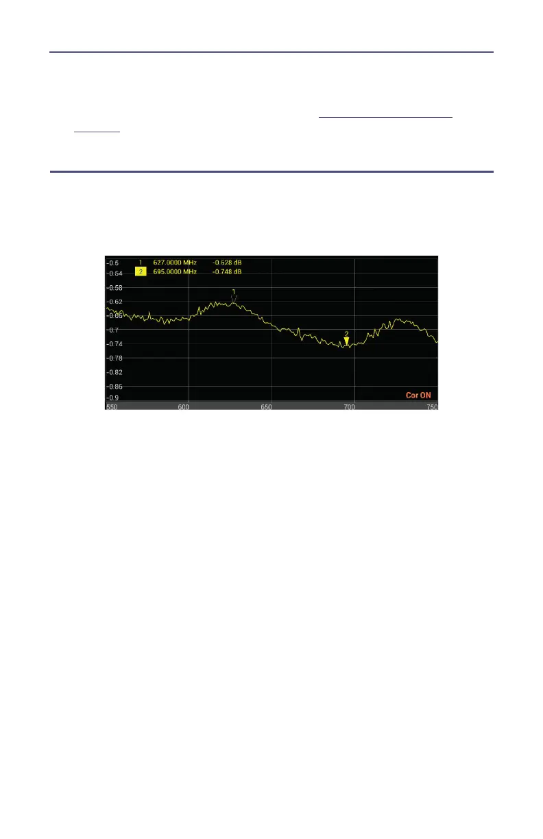
Interpreting a Cable Loss Measurement
The graph below shows a typical cable loss measurement. Note that the scale is
greatly reduced to show the cable’s variation across frequency.
Figure 11 Interpreting Cable Loss Measurement
1. Marker 1 and Marker 2 indicate the minimum and maximum loss for the
cable under test.
2. Take the average of M1 and M2.
Note: This is the average cable loss across the frequency band.
3. Compare the loss with the manufacturer’s specified loss for a cable of this
length.
Note: If they do not correspond, measure the cable loss again, then
check the cable for problems.