KT-230-2 11
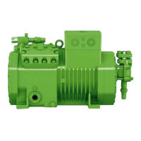
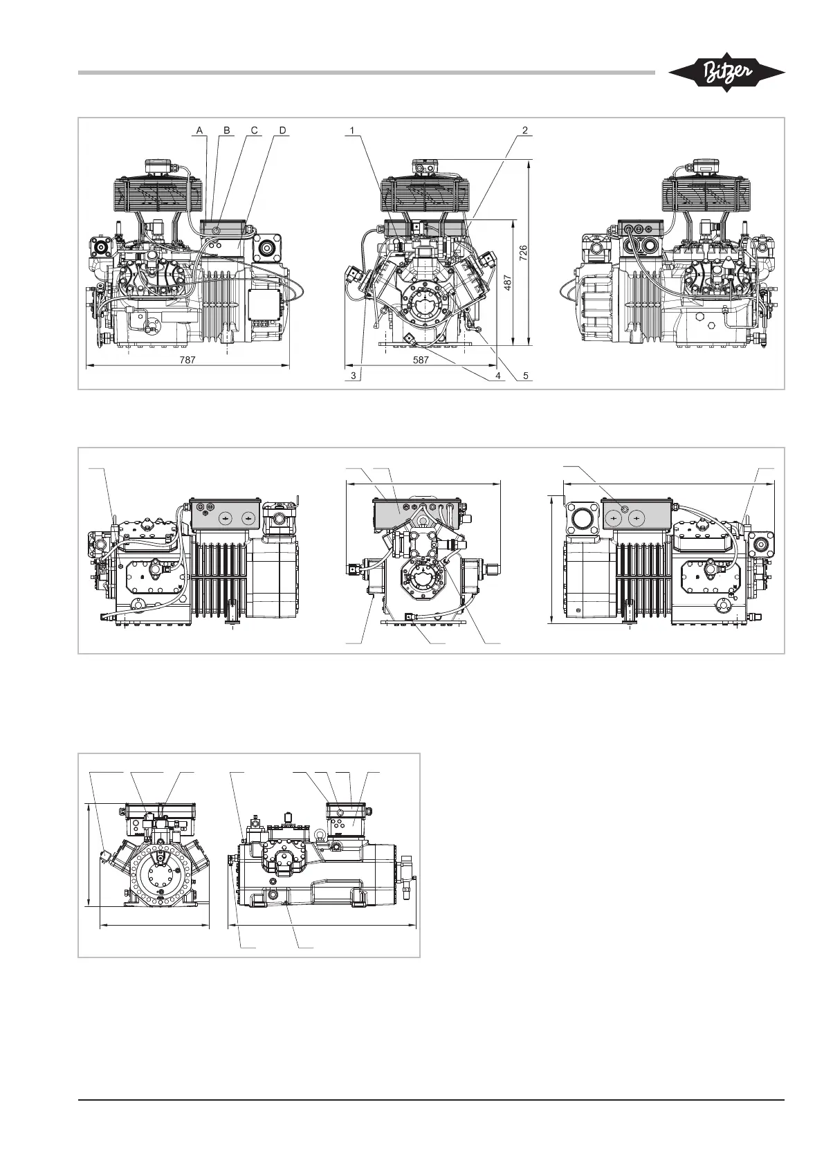
Fig.2: 6JE-22Y .. 6FE-50(Y) with CM-RC-01
The dimensions of the compressors 4VES-6Y .. 4FE-35(Y) with CM-RC-01 differ in a similar way from each standard-version compressor.
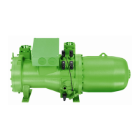
Fig.3: 8GE-50(Y) .. 8FE-70(Y) with CM-RC-01
4.5.2 Dimensional drawings for compressors for
transcritical CO
2
applications with CM-RC-01
CRII(1)
1
Option
CRII(2)
Option
2
4
A B
C
D
5
848
491
469
Fig.4: 6FTE(U)-35(L)K .. 6CTE(U)-50(L)K with CM-RC-01
The dimensions of compressors 4PTE(U)-6(L)K .. 4CTE(U)-30(L)K
with CM-RC-01 differ in a similar way from each standard-version
compressor.
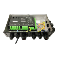
4.6 The refrigerant injection system
The RI system is an operating function of the CM-
RC-01. It injects liquid refrigerant according to require-
ments, thus ensuring the thermal application limits dur-
ing low-temperature applications, such as with refriger-
ants R407A, R407F, 448A and R449A.
When a defined discharge gas temperature is ex-
ceeded, liquid refrigerant is injected directly into the
suction gas chamber of the compressor via the RI in-
jection nozzle. There it flows against the hot cylinder
walls. The liquid refrigerant evaporates, cools the cylin-
der area and simultaneously lowers the temperature of
the superheated suction gas flowing into the engine.
Even with single-stage compression, a sufficiently low
discharge gas temperature is maintained. In case of in-
sufficient cooling or extreme operating conditions, the
CM-RC-01 switches off the compressor.
The design and control of the refrigerant circuit have a
significant influence on the injection cycles and thus on