33
3. When finished, press several times to exit the menu.
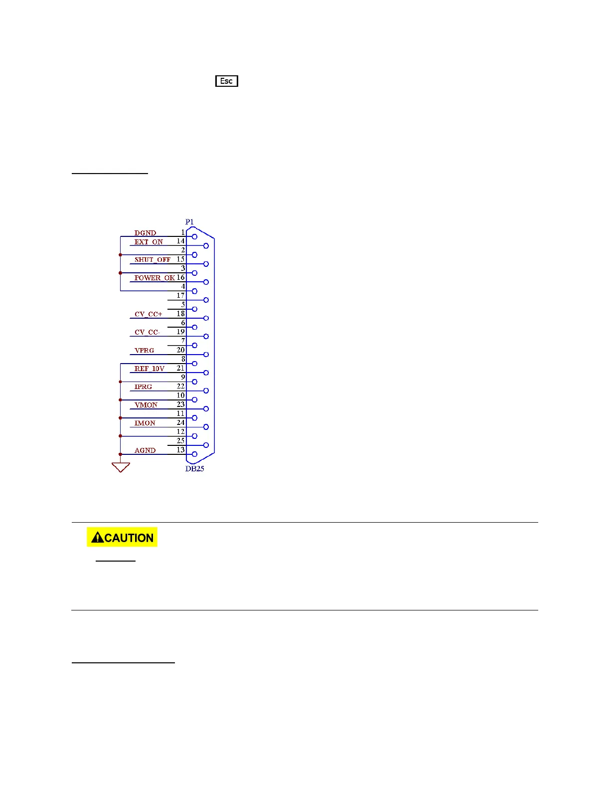
Pin Assignment
Below are the pin assignments of the analog interface.
Figure 3.3 - Analog Interface Pin Assignments
Voltage programming input
Current programming input
Voltage monitoring output
Current monitoring output
DO NOT input any voltages above 10 V DC or 10 kΩ resistance or below 0 V DC to any of
the 25 pins. Doing so will damage the power supply. The inputs also do not have
reverse polarity protection. Check your positive and negative connections carefully first
before feeding power into the control pins.
Control Output State
The output state of the power supply can be controlled by EXT_ON (pin 14) and DGND (pin 1).