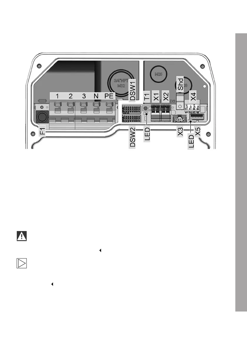
ELECTRICS
Connection diagram with open termination panel cover
1 Mains connection outer conductor 1 T1 Service button
2 Mains connection outer conductor 2 LED Status LED, internal
3 Mains connection outer conductor 3 X1 Enable input
N Mains connection, N conductor X2 RS485 connector
PE mains connection, PE conductor X3 Diagnostic connector, RJ45
F1 Fuse holder X4 Ethernet1 connector, LSA+ terminals
DSW1 DIP switch for configuration X5 USB connector
DSW2 DIP switch for addressing Shd Shield connection for Ethernet1
connection terminals
IMPORTANT
The X3 diagnostic connection is suitable only for error analysis and must not be used to
connect the device to a network.
Note
The connection overview shows all the options of the device, but the legend only lists the
available options. It is possible that your version of the device will not have all the connections
available.
EN
31