EasyManuals Logo

BobsCNC QUANTUM MAX User Manual

Default Icon
176 pages
To Next Page IconTo Next Page
To Previous Page IconTo Previous Page
Page #42 background imageLoading...
Page #42 background image
41
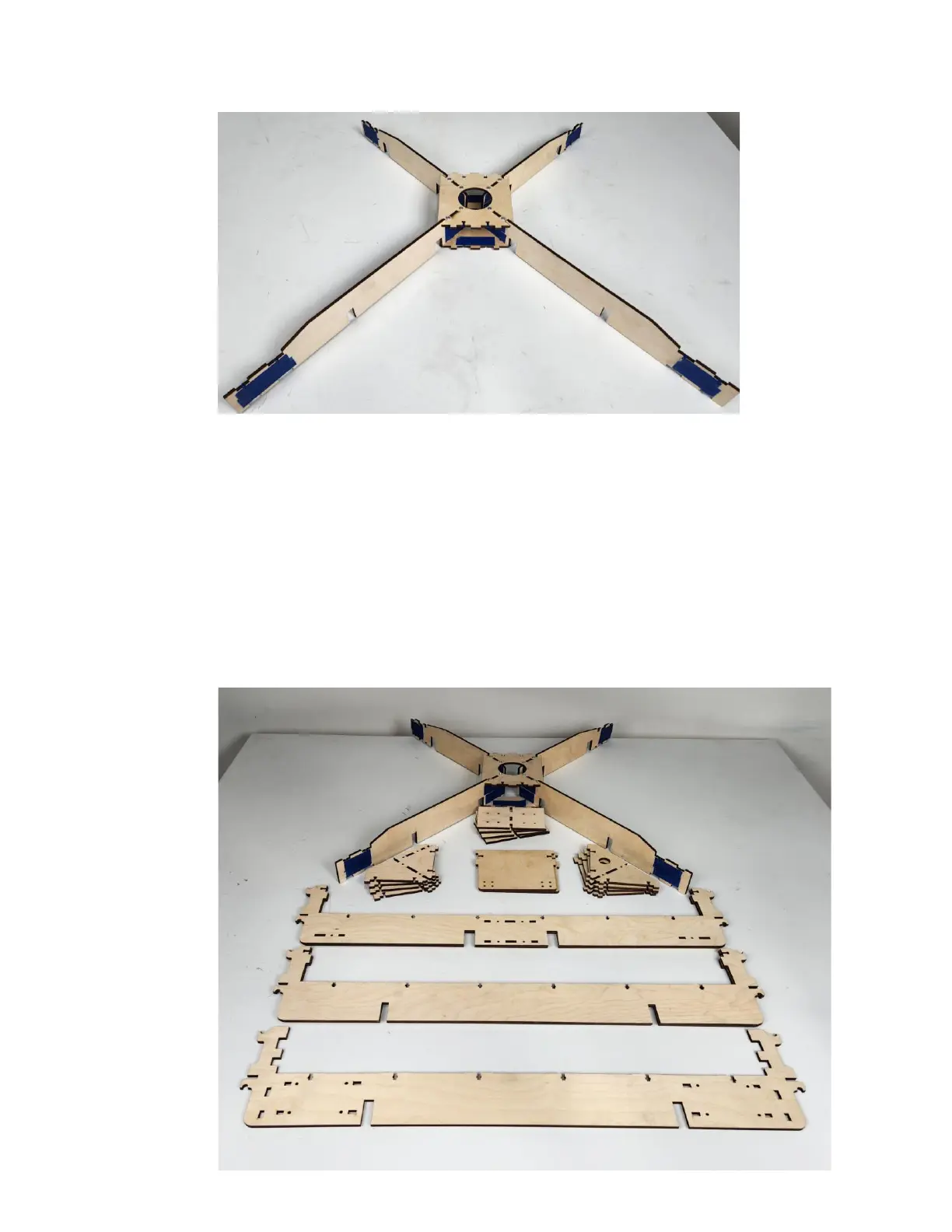
Step 7 Installing the Inner Frame Mid Supports (QX3),
Outer Frame Mid Support (QX4), Wire Harness
Support (QX7), Frame Corner Supports (QX8),
Extension Frame Corner Supports (EQX8), and
Extension Coupling Plates (EQX12).
Step 7a Cover the T-Slots on the inner sides of the
Torsion Plates with strips of painter’s tape to
hold the four M4 x16 Nuts inserted, as shown.
Inner Frame Mid Support
Extension Frame Mid Support
Outer Frame Mid Support

Questions and Answers:

Question and Answer IconNeed help?

Do you have a question about the BobsCNC QUANTUM MAX and is the answer not in the manual?

BobsCNC QUANTUM MAX Specifications

General IconGeneral
BrandBobsCNC
ModelQUANTUM MAX
CategoryControl Systems
LanguageEnglish

Related product manuals