EasyManuals Logo

BobsCNC QUANTUM MAX User Manual

Default Icon
176 pages
To Next Page IconTo Next Page
To Previous Page IconTo Previous Page
Page #48 background imageLoading...
Page #48 background image
47
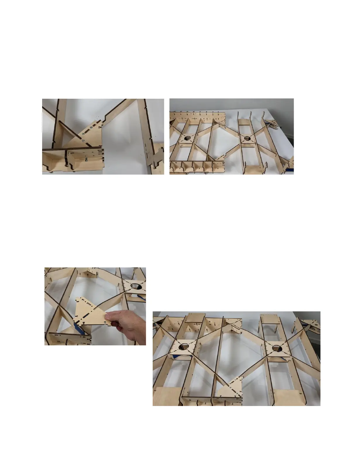
Step 8a Position the Front Assembly to the Rear
Assembly, secure with two M4 x 16
Machine Screws to each side as shown.
Step 8b Gently, flip entire X-Frame Assembly
over and install the remaining two
Extension Frame Corner Supports (EQX8)
to the X-Frame Assembly, as shown and
secure with six M4 x 16 Screws and Nuts.

Questions and Answers:

Question and Answer IconNeed help?

Do you have a question about the BobsCNC QUANTUM MAX and is the answer not in the manual?

BobsCNC QUANTUM MAX Specifications

General IconGeneral
BrandBobsCNC
ModelQUANTUM MAX
CategoryControl Systems
LanguageEnglish

Related product manuals