10.5 Sensor evaluation
In the field of drive engineering, TTL and HTL sensors with 512, 1024 or 2048 divi-
sion marks are widely used. However, other division mark values are used, too.
These division marks (often also referred to as „increments“) determine the resolu-
tion
(accuracy) at which a machine can be operated. A “division mark" is defined as
a pulse including the pause following the pulse – the pulse-
1:1, i.e. with each revolution, a track delivers the number of increments for evalua-
tion. De
pending on the characteristics of the sensor and the requirements in the
machine, different degrees of sensor evaluation accuracy are possible. Typical eval-
uation accuracy levels include:
− Single evaluation: One edge of a pulse of a track is counted and evaluated.
−
Double evaluation: Two edges (the positive and the negative edge) of a pulse of
a track are counted and evaluated.
−
Quadruple evaluation: A second (offset) track delivers additional edges which
can be evaluated. Any status change of the two tracks is registered and evaluat-
ed. Thanks to the offset arrangement of the tracks, the direction of rotation can
be detected additionally. The two tracks are commonly referred to as A and B.
Depending on when the edges occur, it can be determined if the motor ro
in clockwise or in anticlockwise direction.
With double or quadruple evaluation, internal calculation for motor control is im-
proved. The number of division marks does not change.
In addition to tracks A and B, sensors often feature a reference track (also referred
to as Z track, zero track, C track). The reference track delivers one pulse per revolu-
tion. This track is used for plausibility checking or for additional functions.
If an operation mode with reference track is selected for the speed sensor, the fre-
quency inverter will make sure that the Z track occurs according to the parameterized
Division marks, speed sensor 1
491
. If the evaluation is not consistent, a reaction as
per parameter Operation mode 760 is triggered.
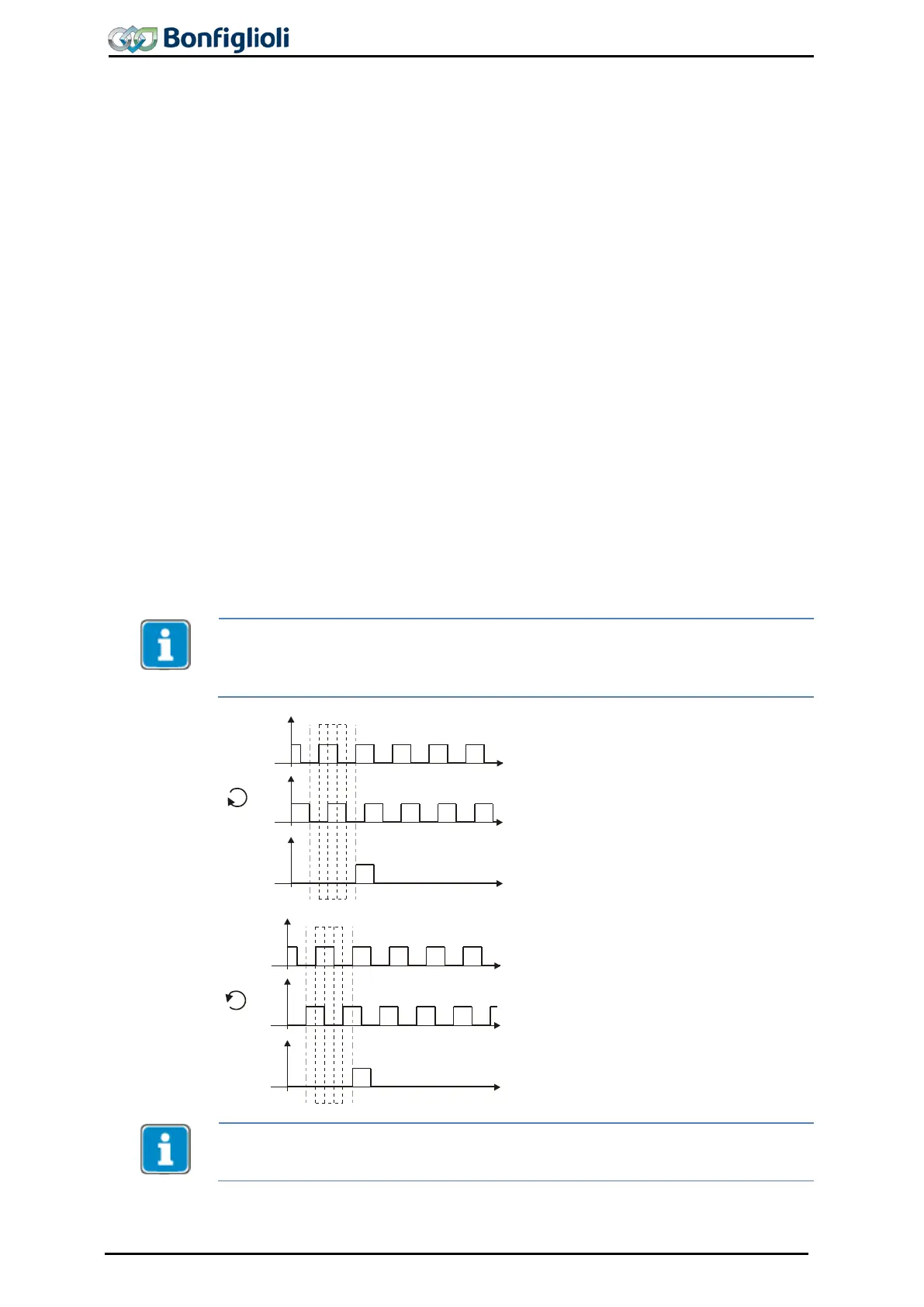
Example (quadruple evaluation):
Each edge 1, 2, 3 and 4 is an evaluated signal
within the pulse-
pause cycle of Track A. After
that, the cycle is restarted. The type of edges
indicates the direction of rotation:
−
Clockwise direction of rotation: A rising
edge of A
(1) is followed by a rising edge
of B (2).
− Anticlockwise direction of rotation A rising
edge of A (1) is followed by a falling edge
of B (2).
Track Z: One pulse per revolution
I HTL sensors can be connected to the basic device. The connection of TTL sensors
requires an expansion module type EM
-
ENC. The connection of SinCos encoders or
Absolute encoders requires an expansion module type EM-ABS.
132 Operating Instructions ACU 06/13
 Loading...
