If the output current has already been reduced due to the fact that the long-term
overload has used up, the short-
term overload is no longer available even if it has not
been used up beforehand. The defined overload reserve (Ixt) of the frequency in-
verter is available again after a power reduction lasting 10 minutes.
Digital outputs can signalize the achievement of a limit value – selected in Operation
Mode 573.
15 - Warning Current Limitation
Intelligent Current Limits active. Output current
is limited.
16 -
Controller Current Limit.
Long Term Ixt
The overload reserve for 60 s has been used up
and the output current is being limited.
17 -
Controller Current Limit.
Short Term Ixt
The overload reserve for 1 s has been used up
and the output current is being limited.
18 - Controller Current Limit. Tc
Intelligent Current Limits active. Maximum heat
sink temperature Tc reached.
19 -
Controller Current Limit.
Motor Temp.
Intelligent Current Limits active. Maximum mo-
tor temperature reached.
17.2 Voltage controller
The voltage controller contains the functions necessary for monitoring the DC link
voltage.
− The DC link voltage which rises in generator
operation or in the braking process
of the 3-phase machine is controlled to the set limit value by the voltage control-
ler.
− The power failure regulation uses the rotation energy of the drive to bridge short-
term power failures.
The voltage controller is set with the parameter Operation Mode 670
in accordance
with the application.
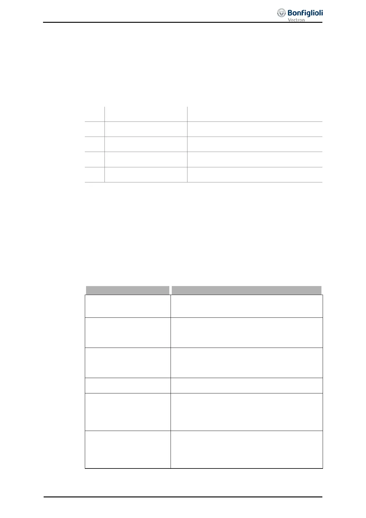
0 - Off
The function is switched off. Brake and Motor chopper
are active and switch with the parameterized thresh-
1 - Udc-Limitation active
DC link limitation active. Overvoltage controller
switched on, the Brake and Motor chopper are active
and switch with the parameterized thresholds of P506
and P507. Factory setting.
2 - Mains Support active
Power failure regulation switched on. Brake and Motor
chopper are active and switch with the parameterized
thresholds of P506 and P507. Suitable for quick shut-
3 -
Udc-Limit. & Mains
Supp. active
Overvoltage controller and power failure regulation
switched on, with motor chopper.
12 -
Mains Support active,
Chopper not active
Power failure regulation switched on. During the
Mains Support, motor and brake chopper are deac-
tivated. In all other cases motor and brake chopper
are active and switch with the parameterized thresh-
13 -
Udc-Limit. & Mains
Supp. active, Chopper
not active
Overvoltage controller and power failure regulation
switched on. During the Mains Support, motor and
brake chopper are deactivated. In all other cases
mot
or and brake chopper are active and switch with
the parameterized thresholds of P506 and P507.
The function motor chopper is available in the field-oriented control methods (in con-
figurations 210, 230, 410, 411 and 430).
06/13 Operating Instructions ACU 211
 Loading...
