15.5.1.1 Timer – Time Constant
The logic sequence of input and output signals is to be set separately for both timer
functions via the time constants. The default parameter values
result in a direct link
of the input and output signal without a delay.
Before starting the timer, select the operation mode and set the time constants in or-
der to avoid non
-defined states.
Select operation mode for:
Operation Mode Timer 1 790
Time 1 Timer 1 791 (signal delay)
Time 2 Timer 1 792 (signal duration)
Operation Mode Timer 2 793
Time 1 Timer 2 794 (signal delay)
Time 2 Timer 2 795 (signal duration)
Parameter Settings
791 Time 1 Timer 1, signal delay 0.00 s/m/h 650.00 s/m/h 0.00 s/m/h
792 Time 2 Timer 1, signal duration 0.00 s/m/h 650.00 s/m/h 0.00 s/m/h
794 Time 1 Timer 2, signal delay 0.00 s/m/h 650.00 s/m/h 0.00 s/m/h
Time 2 Timer 2, signal duration
Examples of the timer function depending on the selected operation mode and the
input signal:
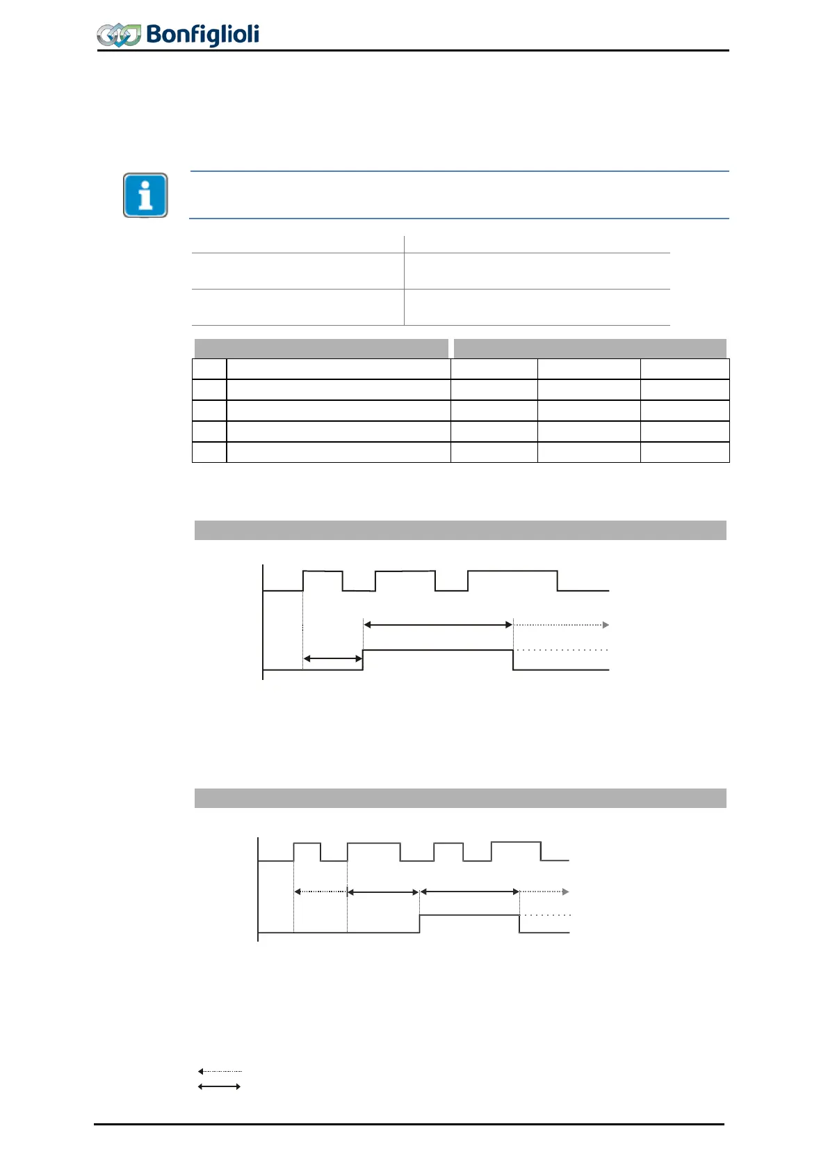
Parameter Operation Mode Timer 1 790 or Operation Mode Timer 2 793 = 1
As soon as the positive signal edge is received at the input, time 1 (signal delay)
starts. After the expiry of time 1 (signal delay), the output signal is switched on for
time 2 (signal duration).
In the settings of signal duration (Time 2 Timer 1 792 = 0 and Time 2 Timer 2 795
= 0) the timer does not reset the output signal.
Parameter Operation Mode Timer 1 790 or Operation Mode Timer 2 793 = 2
As soon as the positive signal edge is received at the input, time 1 (signal delay) is
started. If a positive signal edge is detected within time 1(signal delay), time 1 starts
again. After the expiry of time 1 (signal delay), the out
put signal is switched on for
time 2 (signal duration).
In the settings of signal duration (Time 2 Timer 1 792 = 0 and Time 2 Timer 2 795
= 0) the timer does not reset the output signal.
: Time not run out completely
: Time run out completely
Input
Output
Time 2
Time 1
Factory setting (Time 2 = 0)
Input
Output
Time 2
Time 1
Time 1
Facory setting (Time 2 = 0)
202 Operating Instructions ACU 06/13
 Loading...
