A warning limit allows the user to prevent an imminent I²t-fault trip through appro-
priate measures.
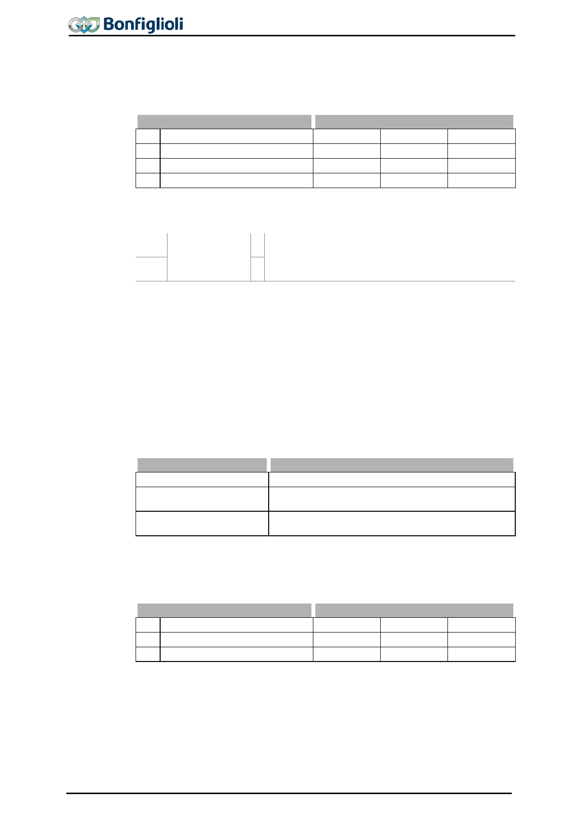
Warning limit motor I
2
t 615 is used to
set the warning signal between 6% and
100% of thermal capacity.
No.
Description Min. Max. Fact. sett.
Thermal time constant Motor
Thermal time constant Stator
Digital signals indicate the triggering of the function “Motor Protection Switch”.
180 -
Warning Motor
Protection
1)
Triggering of the function “Motor Protection Switch”
according to
Operation Mode 571 is signalized.
14 -
2)
1)
For linking with inverter functions
18.6 V-belt Monitoring
Continuous monitoring of the load behavior and thus of the connection between the
3-phase machine and the load is the task of the V-
belt monitoring system. Parameter
Operation Mode 581 defines the functional behavior if the Active Current 214
torque-forming current component Isq 216 (field -
orientated control method) drops
below the set Trigger Limit Iactive 582 for a time longer than the set Delay
The function is deactivated.
1 -
Warning
If the active current drops below the threshold value,
the warning "A8000" is displayed.
2 -
Error
The unloaded drive is switched off and fault message
"F0402" is displayed.
The error and warning messages can be read out by means of the digital outputs
(signal 22 - “Warning V-Belt”) or reported to an overriding control system. The Trig-
ger limit Iactive
582 is to be parameterized as a percentage of the Rated current
371 for the application and the possible operating points.
Parameter Settings
250 Operating Instructions ACU 06/13
 Loading...
