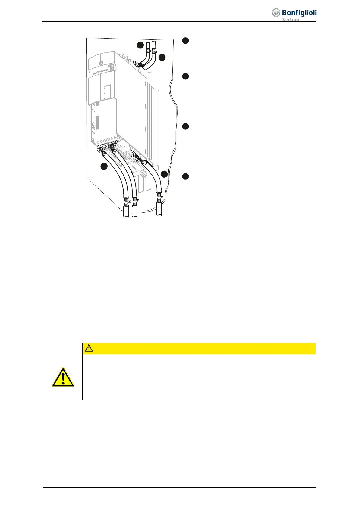
The length of the mains supply cable is not lim-
ited. However, it must be installed separate from
the control, data and motor cables.
The frequency inverters are to be connected to
the same mains potential or a common
direct
voltage source. Cables longer than 300 mm are
to be shielded. The shield must be connected to
the mounting panel on both sides.
Keep control and signal cables physically sepa-
rate from
the power cables. Analog signal lines
are to be con
nected to the shield potential on
one side. Install sensor cables separate from
motor cables.
The shield of the motor cable is to be connected
to ground potential properly on both sides. On
the motor side use a metal compression gland.
On the frequency inverter side an appropriate
shield clamp is to be used. The signal cable used
for monitoring the motor temperature must be
kept separate
from the motor cable. Connect the
shield of this line on both sides. If a brake resis-
tor is used, the connection cable must also be
shielded, and the shield is to be connected to
earth potential on both sides.
Line chokes reduce mains
harmonics and reactive power. Additional the increase of
product life is possible. Consider the reduction of the maximum output voltage if a
line choke is installed.
The line choke must be installed between mains connection and input filter.
Input filters reduce the conducted radio-
frequency interference voltage. The input
filter must be installed upstream on mains side of the frequency inverter.
CAUTION
The frequency inverters meet the requirements of the low-voltage direc-tive
2006/95/EC and the requirements of the EMC directive 2004/108/EC. The EMC prod-
uct standard EN 61800-
3 relates to the drive system. The documentation provides
information on how the applicable standards can be complied if the frequency invert-
er is a component of the drive system. The declaration of conformity is to be issued
by the supplier of the drive system.
06/13 Operating Instructions ACU 51
 Loading...
