Installation
EN
28 bora.com
[1]
Waste water siphon
[2]
Water outlet hose
[3]
Water supply hose
[4]
Fresh water connection
[5]
Waste water connection
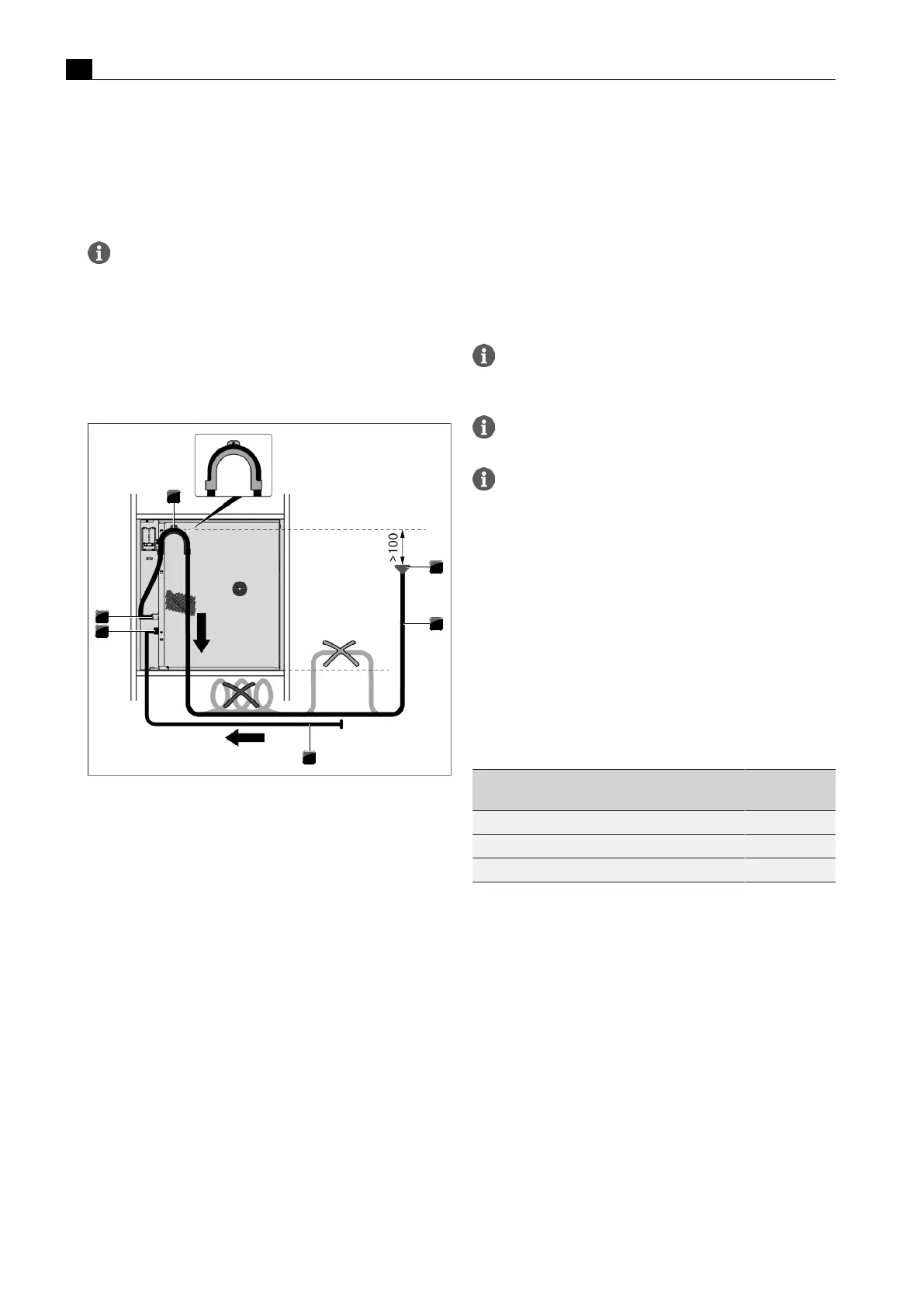
If the waste water trap cannot be installed at least 100 mm
below the waste water connection, the water drainage pipe
must be installed above the hook on back of the appliance. In
doing so, it must be ensured that the waste water trap is
installed at least 100mm below the water drainage pipe in
the hook.
u
Lay the water drainage pipe from the waste water connection so
that it goes up over the hook and then back down.
Fig.9.12
Water drainage via hook
[1]
Waste water trap
[2]
Water drainage pipe
[3]
Water inlet pipe
[4]
Fresh water connection
[5]
Waste water connection
[6]
Hook
9.6.4
Fresh and waste water connection
u
Check that the dirt filter is positioned correctly in the water inlet
pipe.
u
Ensure that there is a washer on each screw connection on the
water inlet pipe and that it is positioned correctly.
u
If necessary, fit a washer.
u
Screw the angled end of the water inlet pipe (facing downwards) to
the fresh water connection on the appliance.
u
Check that it is screwed on tight and is watertight.
u
Using the hose clip, attach the angled end of the water drainage
pipe to the waste water connection on the appliance.
The angled end must be facing downwards. If the pre-assembled
hook on the back of the appliance is used, the angled end of the pipe
must face upwards. The hose clip must only be attached hand-tight.
u
Check that the hose clip is firmly in place.
u
Ensure that there are no kinks in the hoses.
u
Slowly open the stopcock for the fresh water supply and check
that the fresh water connection is tightly sealed.
u
If necessary, check that the washer and screw connection are
firmly in place.
9.6.5
Power supply
u
Observe all safety and warning information (see"2Safety").
u
Observe all national and regional laws and regulations as well as
the supplementary regulations of the local utility companies.
The appliances may only be connected to the mains power
supply by certified specialists. The specialist also assumes
responsibility for the proper installation and commissioning.
Connections via plug-in contacts (Schuko plugs) are not
permitted.
Single-phase connection: the appliance complies with the
requirements of IEC 61000-3-12.
This appliance is intended to be operated on a supply network with an
impedance Zmax at the transfer point (mains connection) of 0.0416
ohms maximum. The user is to ensure that the appliance is only
operated on a power supply network which meets this requirement. If
necessary, ask the local energy supply company about the system
impedance.
u
Switch off the main switch/automatic circuit breaker before
connecting the appliance.
u
Secure the main switch/automatic circuit breaker against being
switched back on without permission.
u
Make sure the power to the appliance is disconnected.
u
Connect the appliance exclusively via a fixed connection to a
power supply cable type H 05 VV-F with corresponding minimum
cross-section.
2-phase
connection
Single-phase
connection
Fuse protection
2 x 16 A 1 x 16 A
Maximum power consumption
6100 W 3600 W
Minimum cross-section
2.5 mm
2
2.5 mm
2
Tab.9.2
Fuse protection and minimum cross-section
u
Connect the power supply cable to the power supply of the
appliance in accordance with the relevant connection diagram.
u
Secure the power supply cable with the strain relief clamp.
u
Close the power supply housing cover.
u
Check that installation has been carried out correctly.