12
Subject to change without prior notice Revised 05-12
6 720 220 048
CE Series
• UPM BOARD DEFAULT SETTINGS—Your UPM
board will come from the factory with the
following default settings:
• Freeze—”Terminals not jumped” on all the time
• Temp—30°F
• Lockout—2
• Reset—“Y”
• Alarm—“Pulse”
• Test—“NO”
• Hot/Dry Alarm— “Normally Open (NO)”
Considerations
1. Always check incoming line voltage power supply
and secondary control voltage for adequacy.
Transformer primaries are dual tapped for 208
and 230 volts. Connect the appropriate tap to
ensure a minimum of 18 volts secondary control
voltage. 24 volts is ideal for best operation.
2. Long length thermostat and control wiring leads
may create voltage drop. Increase wire gauge or
up-size transformers may be required to insure
minimum secondary voltage supply.
3. FHP recommends the following guidelines for wiring
between a thermostat and the unit: 18 GA up to 60
foot, 16 GA up to 100 ft and 14 GA up to 140 ft.
4. Do not apply additional controlled devices to
the control circuit power supply without
consulting the factory. Doing so may void
equipment warranties.
5. Check with all code authorities on
requirements involving condensate disposal/
over ow protection criteria.
ELECTRIC HEATER PACKAGE OPTION
The HP series heater package requires its own
electrical service separate from the heat pump’s
power supply. DO NOT attempt to wire the
package into the same circuit as the heat pump.
Factory installed internal electric heater packages
are available for CE series units. Two power supplies
are required when heater packages are utilized. The
power supply for the heater package (located in the
electric heater package control box) provides power
for the heater elements, the blower motor and the
control circuit for the unit. The power supply for the
unit provides power for the compressor. This allows
the electric heaters to continue to operate along with
the blower motor in the case of unit compressor and/
or compressor power supply failure.
Each CE Series
model has a number of heater sizes available. Refer
to Figure #9 for heater package compatibility with
specic CE Series units, models nomenclature and
electrical data.
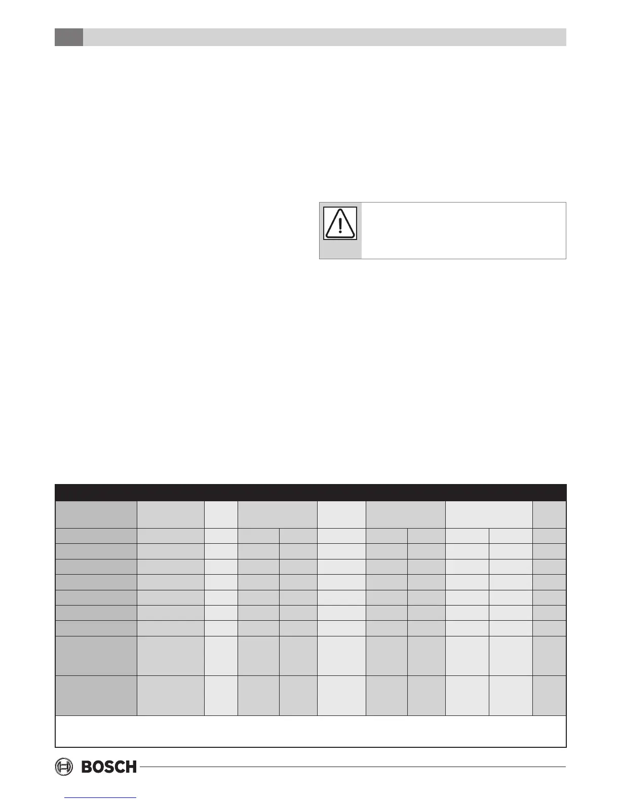
Electric Heater Package Option
Figure 9: Heater Package Compatibility
Model Heater Model KW Heater AMPS Circuit MCA Max. Fuse AWG
Min.
208V 240V 208V 240V 208V 240V
CE025 thru 035 HP050-1XS 4.8 17.3 20.0 L1/L2 27.1 30.4 30 30 8
CE049 thru 071 HP050-1XM 4.8 17.3 20.0 L1/L2 27.1 30.4 30 30 8
CE025 thru 035 HP075-1XS 7.2 23.6 30.0 L1/L2 34.9 42.9 40 45 8
CE049 thru 071 HP075-1XM 7.2 23.6 30.0 L1/L2 35.7 43.8 40 45 8
CE025 thru 035 HP100-1XS 9.6 34.7 40.0 L1/L2 48.8 55.4 50 60 6
CE049 thru 071 HP100-1XM 9.6 34.7 40.0 L1/L2 49.5 56.3 50 60 6
CE049 thru 071 HP150-1XM
HP150-1XM
14.4
14.4
52.0
34.7
17.3
60.0
40.0
20.0
SINGLE
L1/L2
L3/L4
71.2
49.5
21.7
81.3
56.3
25.0
80
60
25
90
60
25
4
6
10
CE049 thru 071 HP200-1XM
HP200-1XM
19.2
19.2
69.3
34.7
34.7
80.0
40.0
40.0
SINGLE
L1/L2
L3/L4
92.9
49.5
43.4
106.3
56.3
50.0
100
50
45
110
60
50
2
6
6
All heaters rated single phase 60 Hz, and include unit fan load. All fuses type “D” time delay or HACR type breaker or
HRC FORM 1. Wire size based on 60 deg. C copper conductors.