6 720 220 048
Revised 05-12 Subject to change without prior notice
7
CE Series
ELECTRICAL
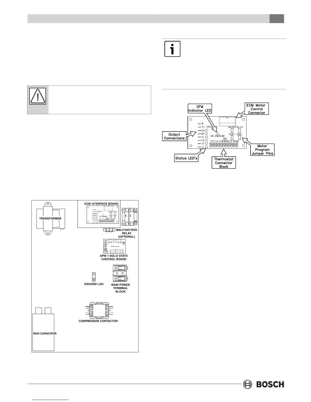
(Refer to electrical component box layout, Figure #5)
Field wiring must comply with local and national
electric codes. Power to the unit must be within the
operating voltage range indicated on the unit
nameplate or on the performance data sheet.
Operation of unit on improper line voltage will
be hazardous to the unit, constitutes abuse
and may void the warranty.
Properly sized fuses or HACR circuit breakers must
be installed for branch circuit protection. See unit
nameplate for maximum fuse or breaker size.
The unit is provided with a concentric knock-out in
the front left corner post for attaching common
trade sizes of conduit, route power supply wiring
through this opening. Always connect the ground
lead to the grounding lug provided in the control box
and power leads to the power supply terminal block
as indicated on the wiring diagram and Figure #5.
Figure #5
SINGLE & TWO STEP
Units supplied with internal electric heat
require two (2) separate power supplies: one
for the unit compressor and one for the electric
heater elements, blower motor and control
circuit. Refer to the ELECTRIC HEATER
PACKAGE OPTION section and Figure #9 for
wiring instructions, minimum circuit ampacities
and maximum fuse/breaker sizing.
ECM INTERFACE BOARD
THERMOSTAT CONNECTIONS
Thermostat wiring is connected to the 10 pin screw
type terminal block on the lower center portion of
the ECM Interface Board. In addition to providing a
connecting point for thermostat wiring, the
interface board also translates thermostat inputs
into control commands for the variable speed
programmable ECM DC fan motor and displays an
LED indication of operating status. The thermostat
connections and their functions are as follows:
Y2 Second Stage Compressor Operation
Y1 First Stage Compressor Operation
G Fan
O Reversing Valve (energized in cooling)
W1 Auxiliary Electric Heat (runs in
conjunction with compressor)
EM/W2 Emergency Heat (electric heat only)
NC Transformer 24 VAC Common (extra
connection)
C1 Transformer 24 VAC Common (primary
connection)
R Transformer 24 VAC Hot
HUM Dehumidication Mode (not used in CE
Series)
Electrical