8
Subject to change without prior notice Revised 05-12
6 720 220 048
CE Series
If the unit is being connected to a thermostat with a
malfunction light, this connection is made at the unit
malfunction output or relay.
If the thermostat is provided with a malfunction
light powered off of the common (C) side of the
transformer, a jumper between “R” and “COM”
terminal of “ALR” contacts must be made.
If the thermostat is provided with a malfunction
light powered off of the hot (R) side of the
transformer, then the thermostat malfunction light
connection should be connected directly to the
(ALR) contact on the unit’s UPM board.
To the left of the thermostat connection block are a
row of 2 red and 4 green LED’s. These LED’s indicate
the operating status of the unit. They are labeled as
follows:
EM (red) Emergency Heat On
W1 (red) Auxiliary Heat On
O (green) Reversing Valve Energized, unit is in
cooling mode
Y2 (green) Second Stage Compressor On
Y1 (green) First Stage Compressor On
G (green) Fan On
Just above the connector block is a single red LED
labeled CFM that will blink intermittently when the
unit is running and may icker when the unit is off.
This LED indicates the air delivery of the blower at
any given time. Each blink of the LED represent
approximately 100 CFM of air delivery so if the LED
blinks 12 times, pauses, blinks 12 times, etc. the
blower is delivering 1200 CFM. Refer to Figure #7 for
factory programmed air delivery settings for the CE
Series.
To the right of the thermostat connection block
is a green LED labeled dehumidify.
Just above and to the right of the thermostat
connection block are four sets of jumper pins
labeled ADJ, DELAY, HEAT and COOL. The ADJ set of
pins are labeled NORM, (+), (-) and TEST. CE units
will all be set on the NORM position from the factory,
however, airow can be increased (+) or decreased
(-) by 15% from the pre-programmed setting by
relocating the jumper in this section. The TEST
position is used to verify proper motor operation. If a
motor problem is suspected, move the ADJ jumper
to the TEST position and energize G on the
thermostat connection block. If the motor ramps up
to 100% power, then the motor itself is functioning
normally. Always remember to replace the jumper to
NORM, (+) or (-) after testing and reset the unit
thermostat to restore normal operation.
Do not set the ADJ jumper to the (-) setting
when electric heaters are installed. Doing so
may cause the heaters to cycle on their
thermal overload switches, potentially
shortening the life of the switches.
The other three sets of jumper pins are used to
select the proper program in the ECM motor for the
unit. Refer to Figure #7 for the proper jumper
placement.
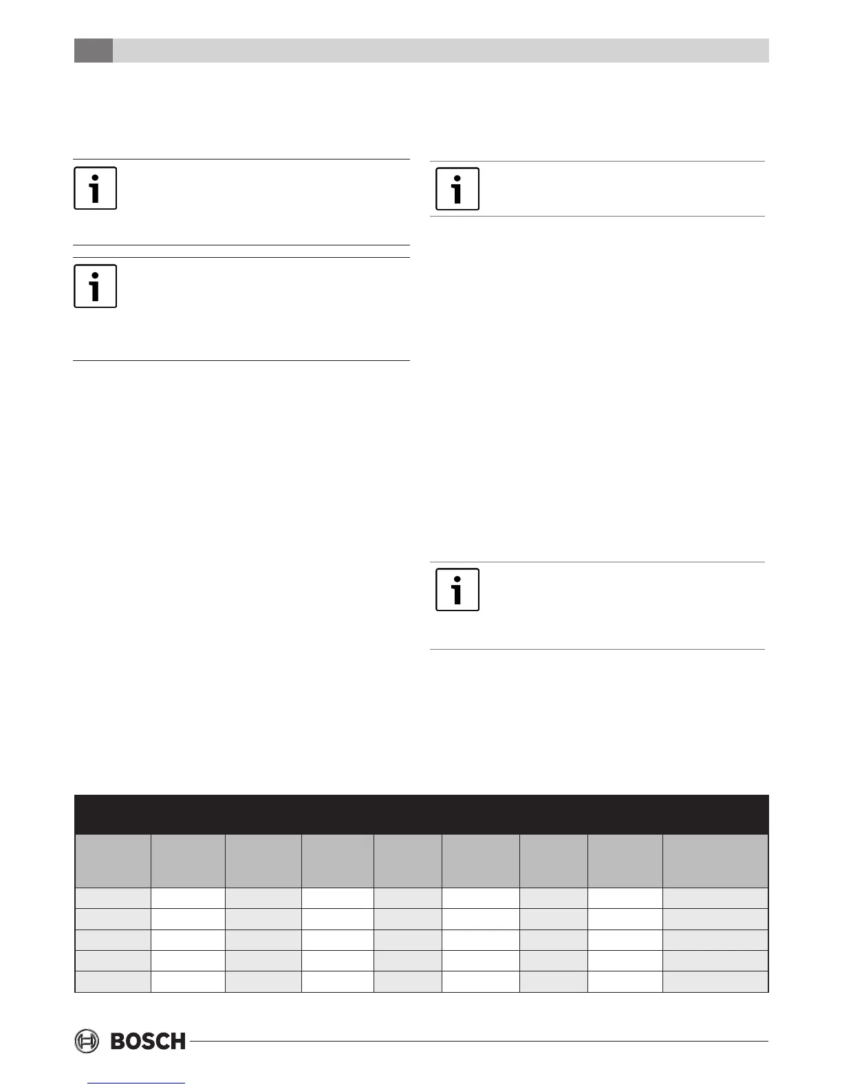
Motor Prole Air Flow Table
Figure 7: Motor Prole Air Flow Table CFM
Two Stage Units
Model Fan
Only
Y1
COOL/
HEAT
Y2
COOL/
HEAT
AUX
HEAT
EMERG
HEAT
PLUS
ADJ
MINUS
ADJ
TAP COOL/
HEAT/DELAY
CE025 450 500 800 800 800 900 700 A
CE035 700 800 1200 1200 1200 1400 1000 A
CE049 900 1000 1600 1600 1600 1800 1400 B
CE061 1200 1400 2000 2000 2000 2100 1900 A
CE071 1600 1600 2200 2200 2200 2300 1900 A