16 en | Quick install Digital Video Recorder 440/480 Series
AM18-Q0605 | v2.0 | 2012.04 Installation and Operation manual Bosch Security Systems
3 Quick install
To get the unit quickly operational, make the connections described below and then enter the
relevant data in the Quick install menu. The Quick install menu appears the first time the unit
is started.
3.1 Connections
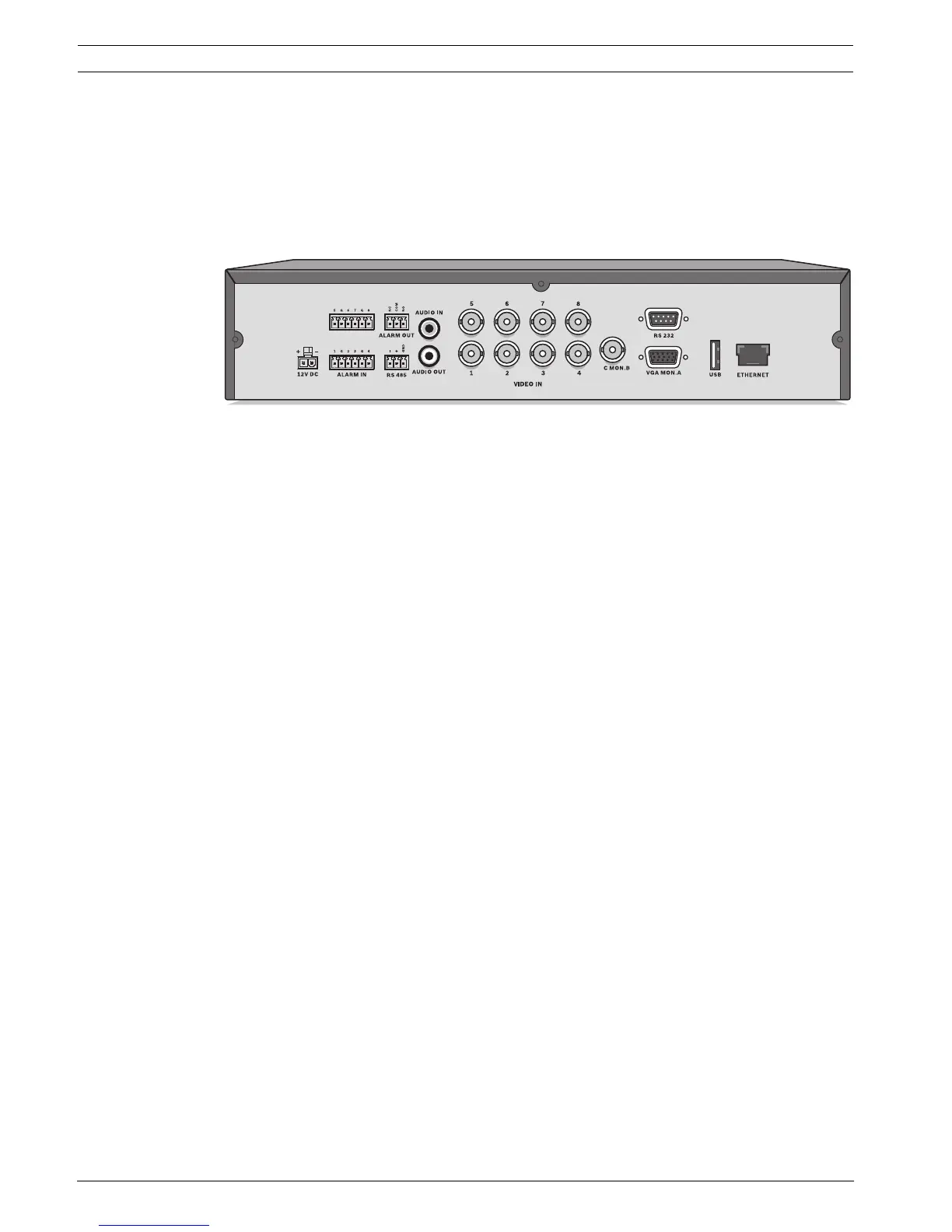
Figure 3.1 Back panel connections for the 4-channel model*
3.1.1 Primary connections
1. Connect the cameras to the VIDEO IN BNC connectors.
2. Connect monitor A to the VGA MON A output (supporting 800x600, 1024x768, or
1280x1024).
3. Connect a USB mouse to the USB port.
3.1.2 Optional connections
1. Connect monitor B to the C MON B BNC connector.
2. Connect an audio signal to the AUDIO IN RCA (CINCH) input.
3. Connect the AUDIO OUT RCA (CINCH) output to the monitor or an audio amplifier.
4. Connect up to 4/8 alarms to the ALARM IN inputs (via the supplied terminal blocks).
5. Connect the ALARM OUT output (via the supplied terminal blocks).
6. Connect a pan/tilt/zoom control unit to the RS-485 port (via the supplied terminal block).
7. Connect to your network via the RJ-45 Ethernet port.
8. Connect a “Bosch RS232 to Bi-phase converter” to the RS-232 port if required.
3.1.3 Powering up
Switch on all connected equipment.
– Connect the power unit to the AC power outlet.
– Connect the DC power cord to the 12VDC connector on the unit.
* 8-channel models have 8 video connectors and 2 alarm input connectors.