Safety Devices and the UPM Controller Overview
When a malfunction light is used for diagnostic purposes, the
connection is made at the unit’s malfunction output—the
Normally Open (NO) dry contact connection terminals of the
UPM board. (Refer to Fig. 8, item [17].)
The safety controls that are monitored by the UPM include the
followi
ng:
• High-pressure switch located in the refrigerant discharge line
and wired across the HPC (High-Pressure Switch
Connection) terminals on the UPM.
• Low-pressure switch located in the unit refrigerant suction
line and wired across the LPC (Low-Pressure Switch
Connection) terminals (LPC1 and LPC2) on the UPM.
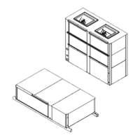
• Waterside freeze protection sensor, mounted close to
condensing water coil, monitors refrigerant temperature
between condensing water coil and thermal expansion valve
or capillary tube. (Refer to Fig. 10.)
NOTICE
Only the compressor protection module is wired in series with
the high-pressure switch (on both the first and second stage
boards).
Fig. 10 Waterside Freeze Protection Sensor Location
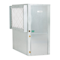
• Air coil freeze protection sensors are mounted close to
evaporator coil between the thermal expansion valve and
evaporator coil. (Refer to Fig. 11.)
Fig. 11 Air Coil Freeze Sensors Locations
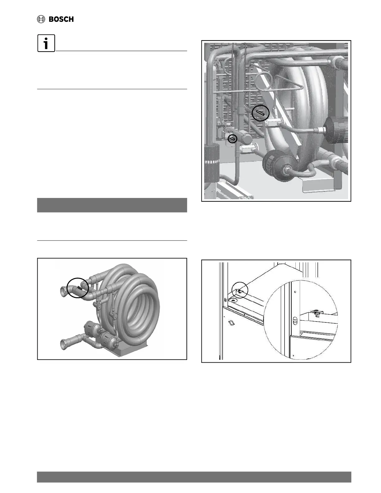
• The condensate overflow switch is standard in all EC units. It
is located in the drain pan of the unit and connected to the
“COND” terminal on the UPM board.(Refer Fig. 12.)
(Refer to Fig. 8, item [15].)
Fig. 12 Condensate Overflow Protection Sensor
| 27
EC Series Heat Pumps — 8733841499 (2024/05)
 Loading...