Safety Devices and the UPM Controller Overview
• HIGH-PRESSURE BYPASS TIMER: If the
compressor is running and the high-pressure switch (either
high-pressure switch 1 or 2, corresponding to the First-Stage
or Second-Stage UPM boards) opens, the controller will shut
down the compressor and keep the compressor OFF until the
switch closes and the anti-short cycle time delay expires. If
the high-pressure switch opens 2 or 4 times (depending on
DIP switch 1 position) within 1 hour then the unit will go to
hard lockout and energize the alarm contact. (
Refer to Fig.
8, item [17].) At any time during a Y1 and/or Y2 call when the
high-pressure switch opens the control will flash the
appropriate fault code.
• BROWNOUT/SURGE/POWER INTERRUPTION
PROTECTION: The brownout protection in the UPM
board will shut down the compressor if the incoming power
falls below 18 VAC. The compressor will remain OFF until the
voltage is above 18 VAC and ANTI-SHORT CYCLE TIMER
(300 seconds) times out. The unit will not go into a hard
lockout and does not need to be reset.
• LED STATUS INDICATOR (Fault Status):
(Refer to Fig. 8, item [6].) The LED Status Indicator
displays either a solid green indicating no faults or will blink a
fault code in red. (Refer to Table 10 for a description of the
blink codes.)
• MALFUNCTION OUTPUT: The alarm output is at the
Normally Open (NO) dry contact. (
Refer to Fig. 8, item
[17].) If “PULSE” is selected, the alarm output will be pulsed.
The fault output will depend on the DIP switch setting for
Alarm. If DIP switch position “3” is set to “ON,” a constant
signal will be produced to indicate a fault has occurred, and
the unit requires inspection to determine the type of fault. If
it is set to "OFF," a pulse signal is produced and a fault code is
detected by a remote device indicating the fault. The remote
device must have a malfunction-detection capability when
the UPM board is set to "PULSE." (Refer to Table 10 for a
description of the blink codes.)
If both UPM boards are flashing fault codes, the flashes will
not be synchronized. Make sure to count the flashes on each
UPM board to know what each are signaling.
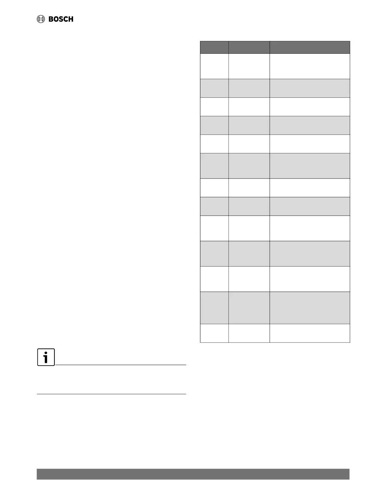
Table 10 UPM Fault Blink Codes
Blinks Fault Fault Criteria
None
(Solid)
None
None.
Adequate 18–30 VAC
power is pr
esent.
1
High Pressure
Sensor #1
Refrigerant discharge pressure has
exceeded 600 PSIG.
2
Low Pressure
Sensor #1
Refr
igerant suction pressure has
fallen below 40 PSIG.
3
High Pressure
Sensor #2
Refrigerant discharge pressure has
exceeded 600 PSIG.
4
Low Pressure
Sensor #2
Refr
igerant suction pressure has
fallen below 40 PSIG.
5
Freeze Sensor #1
Water Coil Freeze
Condition
Refrigerant temperature to the
water coil has fallen below 25°F
for 30 seconds.
6
Condensate
Overflow
Con
densate levels in the unit drain
pan are too high.
7 Brown Out
Control voltage has fallen
below 18 VAC.
8
Freeze Sensor #2
Air Coil Fr
eeze
Condition
Refrigerant temperature to the
air coil has fallen below 25°F
for 30 seconds
9
Freeze Sensor #3
Water Coil Freeze
Condition
Refrigerant temperature to the
water coil has fallen below 25°F
for 30 seconds.
10
Freeze Sensor #4
Air Coil Fr
eeze
Condition
Refrigerant temperature to the
air coil has fallen below 25°F
for 30 seconds
11 Refrigerant Leak
Refrigerant concentration has fallen
outside of acceptable range (above
15% LFL, refer to leak detection
system section)
12
Second-Stage
UPM Board Fa
ult
Lost communications with the
Second-Stage UPM board
| 29
EC Series Heat Pumps — 8733841499 (2024/05)
 Loading...