6 720 643 256 (2010/05)
Installation (for installers only) | 19US/CA
3.2 Making the electrical
connections
3.2.1 Electrical connection in boiler
B Installation of the controls automatically
produces BUS connection via the three
contacts (Æ Fig. 8 on page 14).
Fig. 16 Controls installed in boiler via BUS
contacts in BUS-enabled Heatronic 3.
3.2.2 Electrical connection to wall
B For BUS connection use AWG 18 (0.75 mm
2
)
cable and do not exceed 492 ft. (150 m) total
length.
B For the outdoor sensor AF use AWG 18
(0.75 mm
2
) cable and do not exceed 66 ft
(20 m) total length.
B Route all low-voltage cables separately from
cables carrying line voltage to avoid inductive
interference (minimum separation 4"
(100 mm)).
B In case of inductive external influences, use
shielded cables.
This way, the cables are shielded against
external influences (e.g. high-voltage cables,
contact wires, transformer stations, radio and
TV devices, amateur radio stations, microwave
devices, etc.).
Fig. 17 Controls connected to BUS-enabled
Heatronic 3.
Fig. 18 Connection of BUS links via junction box
A Junction box
B BUS devices
The controls recognize that the
boiler is installed via the third
contact.
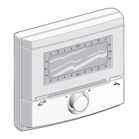
FW 200
1
2
4
BB
6 720 612 481-04.1R
ST 19
Heatronic 3
AF
AF
If the BUS cables feature different
cross-sections:
B Connect BUS link via a junction
box.
FW 200
1
2
4
BB
6 720 612 481-05.1R
ST 19
Heatronic 3
AF
B
B
AF
B
2
BB
A
B
2
BB
B
2
BB
6
720 643 250-08.1O
≥ 4"
(≥ 100 mm)
≥ 4"
(≥ 100 mm)

 Loading...