Technical Data | 2
Bosch Motorsport Engine_Control_Unit_MS_6.x_Manual 21/76
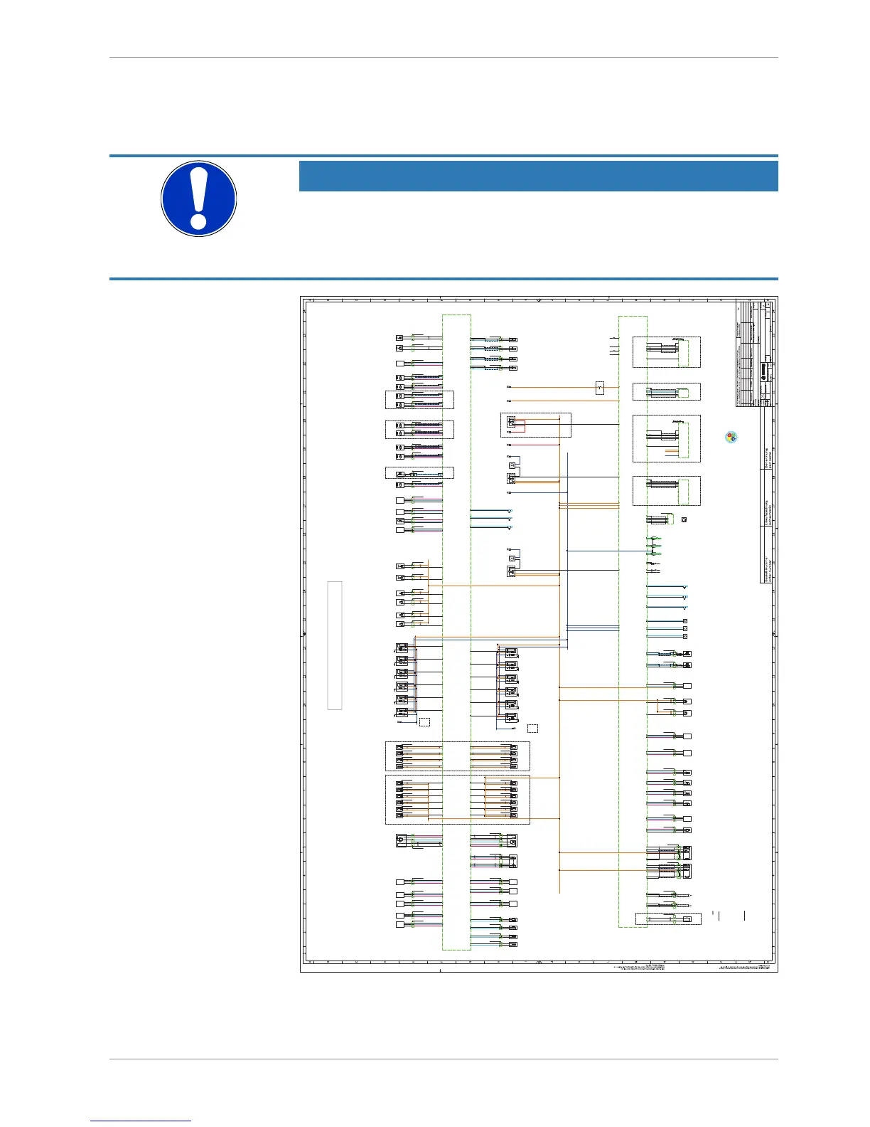
2.3.7 Harness / Wiring
The wiring diagram is available at Bosch Motorsport website on the MS 6 product page.
NOTICE
The wiring diagram shows a principle of wiring and connection op-
tions.
ECU pin relation may change to customer data application and program layout. Sensor-,
actuator- and power supplies may also change to the request of the project.
4 13 2
ENG GND
+
Kl.1
ECU GND
D261 205 336-01
4 13 2
ENG GND
+
Kl.1
ECU GND
D261 205 336-01
4 13 2
ENG GND
+
Kl.1
ECU GND
D261 205 336-01
4 13 2
ENG GND
+
Kl.1
ECU GND
D261 205 336-01
4 13 2
ENG GND
+
Kl.1
ECU GND
D261 205 336-01
4 13 2
ENG GND
+
Kl.1
ECU GND
D261 205 336-01
4 13 2
ENG GND
+
Kl.1
ECU GND
D261 205 336-01
4 13 2
ENG GND
+
Kl.1
ECU GND
D261 205 336-01
Cylinder 1
ignition
2,5mm²
1 2
Injection
valve
Cylinder D
.
1 2
Injection
valve
Cylinder C
.
1 2
Injection
valve
Cylinder B
.
1 2
Injection
valve
Cylinder A
.
1 2
.
.
camshaft
control in
cam
1 2
.
.
camshaft
control in2
cam 2
? ?
not def.
waste gate
control valve
increase bank1
wastegate inc b1
? ?
not def.
waste gate
control valve
increase bank2
wastegate inc b2
1 2
.
.
gearshift
actuator
upshift
upshift
1 2
.
.
gearshift
actuator
downshift
downshift
X1
2 1X2 3
fuel pump
relay
.
r/pump
AWG 14
fuel pump
not def.
pump
AWG 14
X12 1X2 3
main relay
.
r/main
AWG 8
M
+
-
5
+
S1
-
S2
H+
H-
electronic
throttle control
ath
3 4 6 1 2
electronic
throttle control 2
ath 2
M
+
-
5
+
S2
-
S1
H+
H-
31642
.
.
.
.
M
+
-
.
H+
H-
.
? ?
not def.
not def.
deliver
control
valve bank1
fcv 1
? ?
not def.
not def.
deliver
control
valve bank2
fcv 2
H-Bridge
3
oil
temperature
toil
? ?
not def.
not def.
fuel
temperature
tfuel
? ?
not def.
not def.
? ?
not def.
not def.
? ?
not def.
not def.
air
temperature
tint
engine
temperature
tmot
.
Signal
+ -
oil
pressure
sensor
poil
.
.
? ? ?
not def.
not def.
.
Signal
+ -
P21
intake manifold
sensor
p21
.
.
? ? ?
not def.
not def.
.
Signal
+ -
.
.
? ? ?
not def.
not def.
.
Signal
+ -
.
.
? ? ?
not def.
not def.
P21_2
intake manifold
sensor
p21_2
P22
intake manifold
sensor
after throttle
p22
.
Signal
+ -
.
.
? ? ?
not def.
not def.
P22_2
intake manifold
sensor
after throttle
p22_2
S+
-
S+
-
1 2 3 4 5 6
acceleration
pedal
sensor
aps
AS 007-35SN.
AS 607-35PN
launch
function
switch
B_LAUNCHSW
chassis function
reset
switch
B_CHASSISRESSW
pit
speed
switch
B_PITSPEEDSW
map
position
switch
MAPPOS
traction
control
switch
TC_STAGE
wet
switch
B_WET
Signal
+ -
sensor
meas
K48
meas_K48
? ? ?
not def.
not def.
l
a
n
g
i
S
+ -
clutch
pressure
pclutch
? ? ?
not def.
not def.
l
a
n
g
i
S
+ -
laptrigger
beacon
laptrig
1 2 3
ASL 0-06-05-SD
ASL 6-06-05-PD
S+
-
gear
potentiometer
gear
.
.
? ? ?
not def.
not def.
S+
-
gear shift
sensor
gearshift
.
? ? ?
not def.
not def.
S+
-
free meas.
channel A78
meas_A78
.
? ? ?
not def.
not def.
S
+ -
damper position
sensor
rear left
dam_rl
? ? ?
.
not def.
not def.
S
+ -
damper position
sensor
rear right
dam_rr
? ? ?
.
not def.
not def.
? ? ?
not def.
not def.
Signal
+ -
? ? ?
not def.
not def.
brake
pressure
front
pbrake_f
gearbox
pneumatic
pressure
pgearair
? ? ?
.
not def.
not def.
brake pressure
sensor
rear
pbrake_r
? ? ?
.
not def.
not def.
S+
-
steering
angle
potentiometer
steer
.
.
? ? ?
not def.
not def.
. . .
.
.
exhaust gas
temp. sensor1
texh
.
.
exhaust gas
temp. sensor2
texh 2
. . .
a_camctrl_out
cam out
position
a_camctrl
cam in
position
a_camctrl_out2
cam2 out
position
+ S
-
? ? ?
.
.
+ S
-
+ S
-
? ? ?
.
.
? ? ?
.
.
+
-
crankshaft
signal
nmot
N
S
? ? ?
.
.
wheel
speed _fr
vwheel_fr
wheel
speed_fl
vwheel_fl
wheel
speed_rr
vwheel_rr
wheel
speed_rl
vwheel_rl
+ S
-
? ? ?
not def.
not def.
+ S
-
? ? ?
not def.
not def.
+ S
-
? ? ?
not def.
not def.
+ S
-
? ? ?
not def.
not def.
knock
sensor 1
bank 1
KNOCK1B1
knock
sensor 2
bank 1
KNOCK2B1
2 112
.
.
knock
sensor 1
bank 2
KNOCK1B2
knock
sensor 2
bank 2
KNOCK2B2
2 112
.
.
not def.
not def.
not def.
not def.
not def.
not def.
not def.
not def.
+ -
turbo
speed
nTurbo
N
S
? ? ?
not def.
not def.
+ -
N
S
? ? ?
not def.
not def.
163119171536
5538
9091
48 33
47
3534322050
78797677
37 36 91 92
41538990
82
58 5960 61
43
20
64
20
2
20
23
20
3
20
24
20
46
20
67
20
26
95 21 97 93
85 86 87 88
39 77 7838
40
7574
50 49 50 51 52
1713 14 15 16
4562
shift
up
switch
upsw
shift
down
switch
dnsw
76 57
+ S
-
.
.
47
crankshaft
signal
nmot
1 2
Injection
valve
Cylinder E
.
1 2
Injection
valve
Cylinder F
.
2
Injection
valve
Cylinder H
.
1 2
Injection
valve
Cylinder G
.
44
20
65
20
1
20
22
20
4
20
25
20
45
20
66
20
ground terminal
29
CAN_H
12
CAN_L
28
CAN_H
11
CAN_L
27
CAN_H
10
CAN_L
52
RX
53
TX
44
43
4241
B_D_ETH2Rx+
61
B_D_ETH2Rx-
60
B_D_ETH2Tx+
59
B_D_ETH2Tx-
58
B_D_USB_DP
25
B_D_USB_DN
24
G_G_USB_GND
07
O_V_USB_VBUS
08
51
30 13 37
06
14
05
14
03
14
75
20
04
14
02
14
01
14
89
GNDUSBSCR
09
SCN_DATA
26
ground terminal
4 1 3 2
USB Buchse
.
USB
data
stick
USB
5 7
6 8
3
42
1
RJ-45 Buchse
Ansicht von hinten
3 6 1 2
pair_1
pair_2
Ethernet wire
RJ45 ETH Buchse
2121
8181818081
828282828282
82 82
6364
6565
62626262
6262626262
62 626262
17 17 17
7
7
1111
09
09
5
5
xx xx
ETH1_RX+
ETH1_RX-
ETH1_TX+
ETH1_TX-
x
SYNC IN
shield
x
SP/DDU8/C60
AS DD 6-12-41-SN
.
DDU8/C60
Display DDU S2 Plus
AS 6-14-35-SN
DDU S2+
pair_1
pair_2
Ethernet wire
26
pair_1
pair_2
B_F_TIMESYNC
14
2121
4662
54
20
6
12
0606
06
27 28 29
68 69 70 71
OPTIONAL ETHERNET EXTENSION
1 2
.
.
camshaft
control out
cam out
1 2
.
.
camshaft
control out2
cam out 2
102 94
06 08 08
2,5mm²
power supply
ground terminal
ecu
interface
DIAG
57
AWG 8
72
Starter output
5 4847
a_camctrl2
cam2 in
position
+ S
-
.
.
49625 5
OPTIONAL
OPTIONAL
for inductive sensor
LIN-BUS
GND_engine
rc 8mm blue
GND_ENG
short
connection
to
engine block
GND_engine
rc 8mm blue
GND_ENG
F02U.S00.444-03
Basisanschluss MS6F02U.S00.444-03
MS6 Basic Wiring
Achtung : - alle nicht bezeichneten Leitungen sind auf AWG
24 ausgelegt
- kleine Buchstaben sind unterstrichen
- rc = Ringverbinder
- Ethernetkabel mit Spec. CAT5 verwenden
- Firewirekabel nach Standard IEE1394
- jede CAN Verbindung muss mit 60Ω abgeschlossen sein
- bei USB und Ethernetleitung unbedingt auf Paare achten
- Ethernetverkabelung muss seperat geführt werden
- Kabelquerschnitte müssen nach Bedarf angepasst werden
Attention : - all not marked wire´ are AWG24
- small letters are underlined
- rc = ringwire
- use ethernetcable CAT5
- firewirecable as spec IEE1394
- all CAN networks must be terminated with 60Ω
- please respect strictly the pairs while using datawires like USB or Ethernet
- ethernet wire´s must be wired separately
- wire diametre must be adapted depending on usage
short
connection
to
engine block
power supply
ENGINE
on/off
switch
B_ENGON_IN
F02U.B00.712-01
? ? ?? ? ?
OPTIONAL
4 13 2
ENG GND
+
Kl.1
ECU GND
D261 205 336-01
4 13 2
ENG GND
+
Kl.1
ECU GND
D261 205 336-01
30 31
4 13 2
ENG GND
+
Kl.1
ECU GND
D261 205 336-01
4 13 2
ENG GND
+
Kl.1
ECU GND
D261 205 336-01
Cylinder 2
ignition
Cylinder 3
ignition
Cylinder 4
ignition
Cylinder 5
ignition
Cylinder 6
ignition
Cylinder 7
ignition
Cylinder 8
ignition
Cylinder 9
ignition
Cylinder 11
ignition
Cylinder 12
ignition
Cylinder 10
ignition
72 7354
.
l
a
n
g
i
S
+ -
fuel
pressure high
sensor 2
prail 2
.
.
? ? ?
not def.
not def.
.
Signal
+ -
fuel
pressure high
sensor 1
prail
.
.
? ? ?
not def.
not def.
.
Signal
+ -
fuel
pressure low
sensor
pfuel
.
.
? ? ?
not def.
not def.
8079817 57 06
1
1 2
Injection
valve
Cylinder 4
.
1 2
Injection
valve
Cylinder 3
.
1 2
Injection
valve
Cylinder 2
.
1 2
Injection
valve
Cylinder 1
.
1 2
Injection
valve
Cylinder 5
.
1 2
Injection
valve
Cylinder 6
.
98 100 101 96 99 103
1 2
Injection
valve
Cylinder 10
.
1 2
Injection
valve
Cylinder 9
.
1 2
Injection
valve
Cylinder 8
.
1 2
Injection
valve
Cylinder 7
.
1 2
Injection
valve
Cylinder 11
.
1 2
Injection
valve
Cylinder 12
.
42 105 18 20 63 84
OPTION INJECTION LOW PRESSURE OPTION INJECTION HIGH PRESSURE
F02U.B00.711-01
OPTIONAL USB Data Stick
01
Anlage
20140718 HtM . .
BEG/EMS3
.
Connector "A"
AWG 14
AWG 14
AWG 14
10mm2
Kl.30_Motronic
rc 8mm red
Kl.30_Motronic
power supply
OPTIONAL with MAIN RELAY
AWG 14
AWG 14
AWG 14
Signal
+ -
Signal
+ -
1210 10 5 10 5 10
5 10 5 10 5 10 5 1012 12
5 512
12 12
Kl.31
rc 8mm blue
GND
08 0811110909
32 0633 34 35 08 08 06 08 08
OPTIONAL
S
+ -
damper position
sensor
front right
dam_fr
64 64 64
? ? ?
not def.
not def.
1881
S
+ -
damper position
sensor
front left
dam_fl
64
82
CAN wire
CAN wire
CAN wire
26
CAN 3
CAN 2
CAN 1
ext. components with
function request
(gearcontrol, steeringwheel,..)
Components Bosch Motorsport
(ABS,PBX90,MSA-Box,Bypass,HPI)
ext. components
(measure components)
useable for options like
- alternator control
- wiper control
RS232
useable for options like
- telemetry
Connector "K"
LS 1AMP
TRIGGERWHEEL_SIGNAL Output
FLYWHEEL_SiGNAL Output
RPM SIGNAL Output
20150210 HtM
Kl.30_Motronic
rc 8mm red
Kl.30_Motronic
D261.205.356-01
.
twisted pair
twisted pair
236987882286
70716885
lambda sensor Bank1
D261.205.356-01
LSU 4.9
lam_1
1
6
5
234
Nernst
Pump
D261.205.356-01
.
lambda sensor Bank2
D261.205.356-01
LSU 4.9
lam_2
1
6
5
234
Nernst
Pump
twisted pair
twisted pair
2121
turbo
speed 2
nTurbo2
20150218 HtM
9816
CAN1_low
4
CAN1_high
22
SCREEN
10
K LINE
3
Unit_GND
1
PERM.POS.
2
SW .POS.
15
ecu interface
(MSA-Box2)
AS 012-35SN
DIAG
12
11
TERM 15 PIN
ETH_RX-
ETH_RX+
ETH_TX-
ETH_TX+
44
43
4241
26
pair_1
pair_2
Ethernet wire
OPTIONAL DDUS2 PLUSOPTIONAL DIAG
AWG 8
AWG 20
M
+
-
X12 1X2 3
air conditoin
compressor relay
.
R/GEARAIR
AWG 14
air
compressor
not def.
AC
AWG14
AWG 14
56
08
reverse
gear
shift switch
reverse
5512
.
6mm2
.
.
tbd.
tbd.
tbd.
tbd.
tbd.
tbd.
tbd.
+-+-
RED
Tx+
BLUE
Tx-
Yellow
Rx+
GREEN
Rx-
Ethernetwire
4x AWG24
Min bend radius:
dyn: 47mm
stat: 24mm
56
not def.
not def.
not def.
not def.
.
.
not def.
not def.
update APIX
+12V
digital power supply
rc 8mm red
+12V
+12V
engine on sw
rc 8mm red
+12V
AWG 20
RESPECT WIRE SPEC/LENGTH !
- use the right SPECed wire signed
"Ethernetwire"
AWG 20
- twisted / twisted pair
update
Kl.31
rc 8mm blue
GND
M
+
-
AWG 14
AWG14
Kl.31
rc 8mm blue
GND
USB/Ethernet wire
RESPECT WIRE SPEC !
- use the right SPECed wire signed
"Ethernetwire"
- take care about the wire orientation
RESPECT WIRE SPEC !
- use the right SPECed wire signed
"Ethernetwire"
RESPECT WIRE SPEC !
- use the right SPECed wire signed
"Ethernetwire"
RESPECT WIRE SPEC !
- use the right SPECed wire signed
"Ethernetwire"
02
20150505 HtM
update DDU S2+
03
B_D_ETH2Rx+
61
B_D_ETH2Rx-
60
B_D_ETH2Tx+
59
B_D_ETH2Tx-
58
SCN_DATA
26
924 1025
ETH1_RX+
ETH1_RX-
ETH1_TX+
ETH1_TX-
28
SYNC IN
shield
22
pair_1
pair_2
Ethernet wire
B_F_TIMESYNC
14
3
+12V Supply
4
GND
32
+12V Supply
GND
+12V Supply
+12V Supply
 Loading...