English–71 609 929 J60 • (05.12) PS
41 Table stand *
42 "Table stand" attachment set *
43 Winged nut for clamping the saw table extension
44 Quick action clamp
45 Quick release
46 Tightening knob for the quick action clamp
47 Winged nut of the quick action clamp
48 Locking tab
49 Angle indicator (horizontal)
50 Angle indicator (vertical)
51 Power Light lighting unit
52 Winged nut for the clamping of the length stop
53 Screws of the table insert
54 Spindle lock
55 Socket head screw for attaching the saw blade
56 Clamping flange
57 Tool spindle
58 Scale for the bevel angle (vertical)
59 Screw of the angle indicator (vertical)
59 Screw of the angle indicator (horizontal)
61 Protective dust cover
* Not included with all machine versions
Not all the accessories illustrated or described are in?
cluded in standard delivery.
4 MOUNTING
Avoid unintentional starting of the power
tool. During mounting and for all work on
the power tool itself, the main plug must
not be connected to the power source.
Items Included
Also see the illustration of the delivered
items at the beginning of the operating
instructions.
Before putting the power tool into operation, check
that all of the items listed below have been delivered:
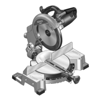
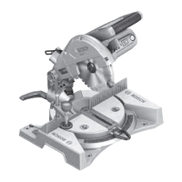
– Compound mitre saw with fitted saw blade
–Dust bag 20
–Locking knob 12
– 2 Extension hoops 6
– "Extension hoop" attachment set 39
(2 Uprofiles with screws)
– Sliding saw table extension 5
– Length stop 38
– Quick action clamp 44
– Allen key / Phillips screwdriver 29
– 3 Batteries (size AAA, 1.5 V)
– Protective dust cover 61
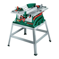
For machine versions with table stand:
–Table stand 41
(16 profiles, 4 caps)
– "Table stand" attachment set 42
(24 screws with nuts for assembly, 4 screws with
nuts for attachment to the power tool, 4 washers)
Check the power tool for possible damage.
Before further use of the power tool, check that all the
protective devices are fully functional. Any lightly dam
aged parts must be carefully checked to ensure flaw
less operation of the tool. All parts must be properly
mounted and all conditions fulfilled that ensure fault
less operation.
Damaged protective devices and parts must be imme
diately replaced by an authorised service centre.
Initial Operation
Remove all parts supplied carefully from the packag
ing.
Remove all packing material from the power tool and
the accessories provided.
To facilitate the work while mounting the machine ele
ments provided, observe that the power tool is in the
transport position.
Tools Required in Addition to those
Delivered
– Phillips screwdriver
–Combination square
– Ring or openended spanner (12 mm)
for assembling the table stand
– Ring or openended spanner (10 mm)
for the basic adjustment of the bevel angle (vertical)
PCM10_WEU.book Seite 7 Donnerstag, 1. Dezember 2005 9:16 09