English–81 609 929 J60 • (05.12) PS
Mounting of the Extension Hoops
(see Figure
)
Mounting the Saw Table Extension and
Length Stop
The saw table extension 5 and the length stop 38 can
be positioned on the left or right of the power tool.
Insert the saw table extension and the length stop as
required on the appropriate extension hoop 6 and
tighten the respective winged nut.
Attaching the Extension Hoops
For attachment, use the "extension hoop" attachment
set 39 (two Uprofiles with screws).
Tip over the power tool so that the extension hoop can
be attached on the underside of the machine.
Hold a Uprofile over an attachment piece on the
housing 40 so that the drillings in both pieces are
aligned.
Slide the extension hoop to the stop through the drill
ings 16, the Uprofile and the attachment pieces on
the housing.
Tighten the screw in the Uprofile to secure the exten
sion hoop.
Repeat the work steps for the second extension hoop
on the other side of the power tool.
Mounting the Locking Knob
(see Figure
)
Screw the locking knob 12 into the threaded hole be
low the lever 11.
Do not tighten the knob too firmly.
Inserting the Batteries
(
see Figure
)
Open the battery compartment 30.
Insert the batteries provided according to the polarisa
tion indicated.
Close the battery compartment.
Stationary Mounting
To ensure safe handling, the power tool
must be mounted on a flat and stabile
working surface (e.g., workbench).
Mounting without the Table Stand
(
see Figure
)
Attach the power tool with suitable screw fasteners to
the working surface. The holes 15 serve for this pur
pose.
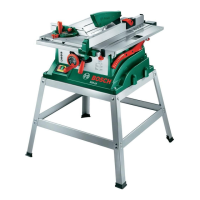
Mounting with the Table Stand
(
see Figure
)
Use the "Table Stand" attachment set 42 for mounting
(24 screws with nuts for assembly, 4 screws with nuts
for attachment to the power tool, 4 washers).
Screw together the table stand 41. Tighten the screws
firmly.
Attach the power tool to the support surface of the ta
ble stand. The drillings 15 on the power tool as well as
the elongated holes in the table stand serve for this
purpose.
5 OPERATING INSTRUCTIONS
Transport and Working Positions
(see Figure
)
Before all work on the machine, pull the mains
plug.
The transport locking pin 27 makes possible easy han
dling of the machine when transporting to the various
working locations.
Securing the Machine (Transport Position)
Tighten the locking knob 12 to lock the saw table 14.
Press the knob 1 (also see Figure ) and, at the same
time, swing the tool arm downward with the handle 2.
Pull the transport locking pin 27 completely out and
turn by 90°. Allow the transport locking pin to engage
in this position.
The tool arm is now securely lock for transport.
Releasing the Machine (Working Position)
Press the tool arm with the handle 2 downward some
what to relieve the load on the transport locking pin.
Pull the transport locking pin 27 completely out and
turn by 90°. Allow the transport locking pin to engage
in this position.
Guide the tool arm slowly upward.
A
B
C
D
E
F
M
PCM10_WEU.book Seite 8 Donnerstag, 1. Dezember 2005 9:16 09