English–111 609 929 J73 • (06.03) PS
Extending the Saw Table
Before all work on the machine, pull the mains
plug.
Long work pieces must be supported at the free end.
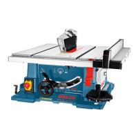
Table Extension/Table Width Extension
(see Figure
)
To enlarge the saw table area, the following rails can
be pulled out at the rear as well as on the right of the
power tool:
– Table extension 2 (extends the saw table 11 to the
rear by 215 mm)
– Table width extension 9 (widens the saw table 11
to the right by 285 mm)
Take hold under the middle of the required rail and pull
out to a maximum of the stop.
To lock in position, tighten the respective attachment
screws on the guide rods.
For heavy work pieces, it may be necessary to provide
support for the rails.
Sliding Table
(
see Figure
)
By means of the sliding table 1, work pieces up to a
maximum width of 305 mm can be sawed. With its
use, a higher precision is also achieved, especially
when sawing in combination with the angle guide 16
(see Section "Sawing Horizontal Mitre Angles with the
Aid of the Sliding Table").
For this purpose, swing the locking lever 23 to the
right. The sliding table can than be slid to the front as
well as to the rear to the stop.
Adjusting the Mitre and
Bevel Angles
Before all work on the machine, pull the mains
plug.
Horizontal Mitre Angle (Angle Guide)
(
see Figure
)
The horizontal mitre angle can be set in the range from
60° (left side) to 60° (right side).
Loosen the locking knob 47 in case it is tightened.
Turn the angle guide until the angle indicator 58 indi$
cates the desired angle.
Retighten the locking knob 47.
Vertical Bevel Angle (Saw Blade)
(see Figure )
The vertical bevel angle can be set in the range of 90°
to 45°. For quick and precise setting of often used
bevel angles, stops are provided at angles of 90° and
45°.
Loosen the locking knob 27 lightly in the counter
clockwise direction.
Caution! When the locking knob is completely loos$
ened, gravity tilts the saw blade to a position that cor$
responds to approx. 30°.
Press the hand wheel 12 to the rear (Push) and hold it
in this position. In this manner, the teeth on the crank
engage the gear ring on the hand wheel.
Turn the hand wheel 12 until the angle indicator 59 in$
dicates the desired bevel angle on the scale 60.
Retighten the locking knob 27.
Adjusting the Parallel Fences
Parallel Fence 7
(
see Figure
)
The marking in the magnifier 61 indicates the spacing
set from the saw blade to the parallel fence on the
scale 13.
Position the parallel fence on the required side of the
saw blades (see also Section "Mounting the Parallel
Fence").
Loosen the clamping handle 41 of the parallel fence
and slide it until the magnifier 61 indicates the desired
distance to the saw blade.
With the rear magnifier and scale, check whether the
parallel fence has been positioned in a straight man$
ner.
To lock, retighten the clamping handle 41.
Parallel Fence 10 on the Table Width Exten-
sion
The parallel fence 10 can be positioned to the left or
the right of the table width extension 9.
Position the parallel fence on the required side of the
table width extension (see Figure ).
The colouring of the sticker on the parallel fence corre$
sponds to the colour of the scale 62 on the front guide
rod. The scale indicates the spacing to the saw blade
depending on the position of the parallel fence.
Take hold of the table width extension 9 under the
middle and pull it out until the desired distance to the
saw blade is indicated on the green or the yellow scale.
C
D
E
F
G
H
PTS10_WEU.book Seite 11 Donnerstag, 23. März 2006 11:47 11
 Loading...
