English–131 609 929 J73 • (06.03) PS
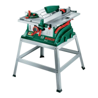
Replacing the Table Insert
The table insert plate 3 can become worn after longer
use of the power tool.
Replace a defective insert plate.
With the enclosed ring spanner 17, lift the insert plate
3 at the front and remove it from the cut$out 42.
Mount the new insert plate.
(See the Section "Mounting the Table Insert")
Sawing
Before all work on the machine, pull the mains
plug.
In case the auxiliary parallel fence 48 is behind the cut$
ting line, loosen the two screws of the attachment set
49 and slide the auxiliary parallel fence.
The distance between the saw blade and the auxiliary
parallel fence can be a maximum of 15 mm.
Sawing Straight Cuts
Set the parallel fence 7 to the required cutting width
(see Section "Adjusting the Parallel Fence").
Place the work piece on the saw table in front of the
protective hood 6.
Raise or lower the saw blade with the hand wheel 12
far enough so that the top saw teeth protrude approx.
5 mm above the surface of the work piece.
Ensure that the protective hood is properly posi>
tioned. When sawing, it must always rest on the work
piece.
Switch on the power tool.
Saw through the work piece with uniform feeding.
Switch off the power tool and wait until the saw blade
comes to a complete standstill.
Sawing Vertical Bevel Angles
Set the desired vertical bevel angle.
Follow the working steps in the Section "Sawing
Straight Cuts" accordingly.
Sawing Horizontal Mitre Angles with Locked
Sliding Table
(also see Figure )
Set the desired horizontal mitre angle with the aid of
the locking knob 47.
The angle guide must be freely movable in the guide
groove 20 (left or right). For this purpose, loosen the
locking knob 46 as required.
Follow the working steps in the Section "Sawing
Straight Cuts" accordingly.
Sawing Horizontal Mitre Angles with the Aid
of the Sliding Table
Set the desired horizontal mitre angle with the aid of
the locking knob 47.
Swing the locking lever 23 to the right and pull the slid$
ing table 1 to the front.
Position the angle guide 16 in front of the work piece
in the left guide groove 20. Lock it in this position by
turning the locking knob 46 in the clockwise direction.
Follow the working steps in the Section "Sawing
Straight Cuts" accordingly.
Checking and Adjusting Basic
Adjustments
Before all work on the machine, pull the mains
plug.
To ensure precise cuts, the basic adjustments must be
checked and adjusted as necessary after intensive us$
age.
Vertical Standard Bevel Angles (90°, 45°)
Place the power tool in the working position.
Set the vertical bevel angle to 90°.
Checking: (see Figure
)
Place a combination square set to 90° on the saw ta$
ble 11. The leg of the square must be flush with the
saw blade over its entire length.
Adjusting: (see Figure )
Loosen the locking knob 27 and hold the saw blade in
the 90° position with the aid of the hand wheel 12.
Loosen the adjustment screw 64 lightly and retighten
the locking knob 27.
Turn the adjustment screw in or out until the leg of the
combination square is flush with saw blade over its en$
tire length.
Then firmly retighten the locking knob 27.
In case the angle indicator 59 is not aligned with the 0°
mark on the scale 60, loosen the screw 66 with a com$
mercially available Phillips screwdriver and align the
angle indicator with the 0° mark.
Repeat the work steps described above accordingly
for the vertical bevel angle of 45° (loosen the locking
knob 27; adjust with the adjustment screw 65). For
this, the angle indicator 59 should not be readjusted.
L2
M1
M2
PTS10_WEU.book Seite 13 Donnerstag, 23. März 2006 11:47 11

 Loading...