BoschRexrothAG, RE 92802-01-B/2023-03-27
20/60 A15VSO/A15VLO series 12 | About this product
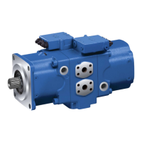
5�2�2 Functional description
Torque and rotational speed are applied to the drive shaft (1) by adrive motor.
The drive shaft is connected to the cylinder (9) by splines, causing the cylinder to
rotate. With every revolution, the pistons (10) perform astroke in the cylinder
bores, the size of which depends on the pitch of the cradle (12). The slipper
pads(11) are held on with the pistons and guided along the glide surface of the
cradle by the retaining plate (2). The pitch of the swashplate during arevolution
causes each piston to move over the bottom and top dead centers and back to its
initial position. Hydraulic uid is fed into and out through two control slots in the
control plate (7) according to displacement. Hydraulic uid ows into the piston
chamber as the piston recedes on the suction side (8). At the same time, the
hydraulicuid is pushed out of the cylinder chamber into the hydraulic system by
the pistons on the high-pressure side (3).
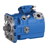
The swivel angle of the cradle (12) is innitely variable. Adjusting the swivel angle
changes the piston stroke and, with it, the displacement. The swivel angle is
controlled hydraulically by means of the stroking piston. The cradle is mounted in
swivel bearings for smooth operation, and it is kept in balance by the opposed
piston (not illustrated). Increasing the swivel angle increases the displacement;
reducing the angle reduces displacement accordingly.
Various control devices are available depending on requirements.
Information about this can be found in data sheet 92802�
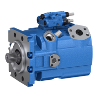
The axial piston unit A15VLO is equipped with acharge pump(4). The charge
pump (impeller) is acentrifugal pump with which the pump is lled and can be
operated at higher rotational speeds. This also facilitates cold starting at low
temperatures and high viscosity of the hydraulic uid. Externally increasing the
inlet pressure is therefore unnecessary in most cases. Charging the reservoir with
compressed air is not permissible.
M
A
A P
V
g min
V
g max
S M T
2
T
3
T
1
4
Fig� 3: Circuit diagram A15VLO with charge pump
Pump function
Control
Charge pump (optional)
 Loading...